background image

Micro Series

1-68  Micro Series

Document generated: 29.06.17

SW V1.1


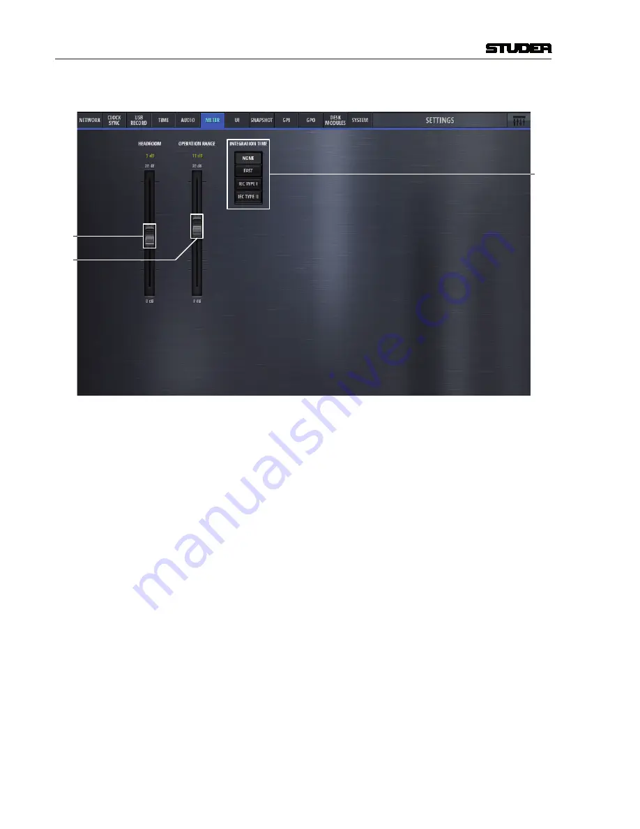
  On the Meter tab, the parameters of the mixer internal metering can be set.

[3]

[1]

[2]


[1] 

Headroom

  Sets the top, red area of the meter. The default value is 9dB, this means that 

meter values above -9dBFS are then displayed in red meter bar elements.


[2] 

Operation Range

  This is the mid section of the meter where the signal is displayed in green 

meter bar elements. 


  Meter bar elements below the operation range are yellow.


[3] Integration Time

  Sets the meters integration time.


None

  0 ms


Fast

  1 ms


IEC Type I

  5 ms


IEC Type II

  10 ms


Summary of Contents for Micro Series

Page 1: ...Studer Micro Series SW Version 1 1 Operating Instructions ...

Page 2: ...ty assumed for any loss or damage resulting either directly or indirectly from use of the information contained within it Prepared and edited by Copyright by Studer Professional Audio GmbH Studer Professional Audio GmbH Technical Documentation Riedthofstrasse 214 CH 8105 Regensdorf Switzerland http www studer ch Subject to change Studer is a registered trade mark of Studer Professional Audio GmbH ...

Page 3: ...ed when the apparatus has been damaged in any way such as the power supply cord or plug is damaged liquid has been spilled or objects fallen into the apparatus the apparatus has been exposed to rain or moisture does not operate normally or has been dropped Note It is recommended that all maintenance and service on the product should be carried out by Studer or its authorised agents Studer cannot a...

Page 4: ...nd to comply with the limits for a Class A digital device pursuant to Part 15 of the FCC Rules These limits are designed to provide reasonable protection against harmful interference when the equipment is operated in a commercial environment This equipment gen erates uses and can radiate radio frequency energy and if not installed and used in accordance with the instruction manual may cause harmfu...

Page 5: ...clamation point within an equilateral triangle is intended to alert the user to the presence of important operating and maintenance servicing instructions in the literature accompanying the appliance Headphones safety warnings contain important information and useful tips on headphone outputs and monitoring levels Assemblies or sub assemblies of this product can contain opto electronic devices As ...

Page 6: ... any way during operation e g by objects placed upon them placement of the unit on a soft surface or installation of the unit within a rack or piece of furniture The unit must not be heated up by external sources of heat radiation sun light spotlights B3 Earthing and Power Supply Earthing of units with mains supply class I equipment is performed via the protective earth PE conductor integrated in ...

Page 7: ...vided earth terminal if one or more external signals are connected to the unit see expla nation at the beginning of this paragraph B4 Electromagnetic Compatibility EMC The unit conforms to the protection requirements relevant to electromagnetic phenomena that are listed in guidelines 89 336 EC and FCC part 15 The electromagnetic interference generated by the unit is limited in such a way that othe...

Page 8: ...upling can be improved by an additional conducting surface in the operator s area connected to the equipment housing e g metal foil underneath the floor covering carpet with conduc tive backing C Maintenance All air vents and openings for operating elements faders rotary knobs must be checked on a regular basis and cleaned in case of dust accumulation For cleaning a soft paint brush or a vacuum cl...

Page 9: ...pair By removing housing parts or shields energized parts may be exposed For this reason the following precautions must be observed Maintenance may only be performed by trained personnel in accordance with the applicable regulations The equipment must be switched off and disconnected from theAC power outlet before any housing parts are removed Even if the equipment is disconnected from the power o...

Page 10: ...k PCB 3 2 1 3 2 1 F Disposal Packing Materials The packing materials have been selected with environmental and disposal issues in mind All packing material can be recycled Recycling packing saves raw materials and reduces the volume of waste If you need to dispose of the transport packing materials please try to use recyclable means Used Equipment Used equipment contains valuable raw materials as ...

Page 11: ...ents of the Canadian Interference Causing Equipment Regulations Cet appareil numérique de la ClasseArespecte toutes les exigences du Règle ment sur le matériel brouilleur du Canada Caution Any changes or modifications not expressly approved by the manufacturer could void the user s authority to operate the equipment Also refer to relevant information in this manual G2 CE Declaration of Conformity ...

Page 12: ...al maximum 10 K increase at the hot components In order to dissipate 1 kW with this admissible average heat increase an air flow of 2 65 m min is required Example Arack dissipating P 800 W requires an air flow of 0 8 2 65 m min which corresponds to 2 12 m min If the cooling function of the installation must be monitored e g for fan failure or illumination with spot lamps the outgoing air temperatu...

Page 13: ...surface always remains below 100 Ensure that the enclosed air is as dry as possible when powering off i e before switching off in winter aerate the room with cold dry air and remove humid objects such as clothes from the room These relationships are visible from the following climatogram For a con trolled procedure thermometer and hygrometer as well as a thermometer within the system will be requi...

Page 14: ... Recommended application temperature range is 20 C to 40 C Remove the plastic protective backing from the rear side of the clamp and apply it firmly to the surface at the desired position Allow as much time as possible for curing The bond continues to develop for as long as 24 hours For improved stability the clamp should be fixed with a screw For this purpose a self tapping screw and an M4 bolt a...

Page 15: ...stem and or its options at the time of delivery to the Customer but have not been developed by Studer The following conditions are applicable to programs of third parties The right to use third parties programs is governed by the License Agree ment attached hereto if applicable which is an integral part of this Agreement The Customer shall sign any and all License Agreements for all further progra...

Page 16: ...ng to the paragraph above by appropriate defense measures against unauthorized access This obligation of non disclosure is a perpetual obligation Third parties are entitled to have access to the License Material if they use the License Material at the Customer s site in compliance with this Agreement Under no circumstance are third parties entitled to have access to the instal lation software on t...

Page 17: ...0 1 7 Applications 10 1 7 1 Hookup Diagram Application 1 Radio OnAir Production 10 1 7 2 Hookup Diagram Application 2 TV OnAir Production 11 1 7 3 Hookup Diagram Application 3 Post Production 12 2 GUI Operation 13 2 1 L1 The operation level for DJs 13 2 1 1 Main Page 13 2 1 2 Mixer Channels 15 2 1 2 1 Channel Roles 15 2 1 3 Chan View 16 2 1 4 Send View 19 2 1 5 Sum View 20 2 1 6 Play er View 21 2 ...

Page 18: ... config 42 2 3 2 Bus Config 52 2 3 3 CR Monitoring Config 57 2 4 Settings view 60 3 Setup 78 3 1 Setting up the Network 78 3 2 Setting up the Micro Fader modules 78 3 3 Setting up the Monitoring 79 3 4 Setting up TB 81 3 5 Setting up N 1 Sends 82 3 6 Setting up GPIOs 82 3 7 Setting up Dante 84 3 8 Firmware update 84 4 Blockdiagram 85 5 Technical Specifications 86 6 Glossary 87 ...

Page 19: ...blet notebook or desktop computer iOS Android Windows MacOS and Linux platforms are supported For local operation a computer screen and mouse and keyboard can be directly connected to the Micro Core to operate the GUI For users who wish dedicated hardware controls the Micro Core can be combined with one or two desk modules adding faders buttons and channel displays for real hands on control The de...

Page 20: ...d and is ready for operation 1 2 1 2 Front side status LEDs The Core Status indication LEDs are described in the table below Status Colour Description Power AC Green AC Power OK Power DC Green DC Power OK Core Ready Green Core started up and ready for operation Error Red The system detected an error or warning Refer to the Error Status page for more details Wi Fi Blue Illuminated as long as Wi Fi ...

Page 21: ...dphones Networked audio I O 2 x AES67 Dante 4 audio channels each Other connectors Mains power DC Power Word Clock In and Out GPIO Ethernet HDMI and 2x USB for GUI 2x RJ45 including PoE for Micro Fader modules 1 2 1 4 Mains Power The Micro Core is primarily powered by an integrated wide rangeAC power supply with IEC type standard connector For mobile use automotive battery or power redundancy an a...

Page 22: ... row Text 0 the functions of the channel specific buttons onrrrr the second row The background of the function name is inverted when the function is active Channel On Master status by changing the backlight colour from white default to blue The backlight is flashing if a channel that is On Master is pending on snapshot parameter recall Buttons The Micro Fader module features six buttons per channe...

Page 23: ... or DOWN This means that the fader must be moved the value in dB s up or down to match the current fader value of the GUI The larger the value the longer the way that the fader needs to be moved until the current fader value is met Since the value is being udated while the fader is moved it is easy to fade to the area where the value becomes 0 Once the fader is there the display indicates that Aut...

Page 24: ...s The only requirement is a network connection to the Micro Core this can either be via wireless LAN or via a wired LAN connection to the Micro Core s Ethernet port Once the webbrowser has been directed to the Micro Core s IP address the control screen is loaded and control elements which are optimized for touch screens with multitouch operation allow to control the mixer Note For browser control ...

Page 25: ...eded This connection can also be made via a corporate network or even via Internet Corporate Network Internet OnAir Micro Base Unit Control device OnAir Micro Base Unit Ethernet cable Control device OnAir Micro Base Unit Control device Of course the Micro Core can also be controlled by a wireless device when connecting an external WLAN router to the Micro Core s network port OnAir Micro Base Unit ...

Page 26: ...ow the full image and no overscan is applied 1 7 Applications 1 7 1 Hookup Diagram Application 1 Radio OnAir Production Dante Unit Codec Tel Hybrid 1 Intercom Matrix Panel Tuner Flash Recorder Player CD Recorder Player OnAir Redlight Control PC WLAN Router Tablet Headphone Headphone Headphone Mic Tel Hybrid 2 Mic Mic DJ GUEST 1 GUEST 2 Dante Unit Analogue Audio Digital Audio Dante GPIO Ethernet PS...

Page 27: ...udio Digital Audio Dante GPIO Ethernet Panel Panel CR Mon Speaker CR Mon Speaker Micro Core RF Receiver RF Receiver RF Receiver RF MIC RF MIC RF MIC IEM Transmitter IEM Video Player 1 Video Player 2 Video Player 3 OnAir Redlight Studio LS Word Clock Program Embedder STUDIO Control PC Master Clock The diagram above shows an example of how the Micro Core could be con nected in a typical TV productio...

Page 28: ...oduction Analogue Audio Digital Audio Dante GPIO Ethernet CR Mon Speaker CR Mon Speaker Micro Core Word Clock Control PC R 128 Meter DAW 1 DAW 2 WLAN Router Tablet Voice Over Booth Codec Reverb The diagram above shows an example of how the Micro Core could be con nected in a typical Post Production environment ...

Page 29: ...Options level only shows the options of one specific channel It is opened by double clicking or touching the channel s label L3 The Configuration level is entered by using the Config button Then the Config view is shown which consists of several pages In the following chapters all three levels are described 2 1 L1 The operation level for DJs 2 1 1 Main Page For basic DJ operation all necessary con...

Page 30: ...by the view buttons in the central section This section is the main working surface for the DJ Central Section The section in the middle of the GUI provides the view buttons elements for navigation the OnAir indication as well as the button to access the mixer settings Right Section The right section of the GUIs operation view displays control elements for Watch Recording Snapshot handling Meterin...

Page 31: ...or sends 3 the bus owner of a N 1 bus Talk Input for sends 4 the bus owner of a N 1 bus Talk Track for the input channel that is linked to the Track Player Next Display Is linked to USB In 3 4 Jingle for the input channel that is linked to the Jingle Player Jingle buttons Is linked to USB In 1 2 Already in the factory reset state of the mixer the channels have different roles Channel Number Channe...

Page 32: ... between the faderstrips The operating elements that are common to all channels are these channel role Default 1 2 3 4 5 6 1 Label The channel label display shows the channels name This name can be entered in the Options page of the channel The labels background changes from grey to blue when the channel is On Master 2 Rec button The Rec button assigns a channel to the record bus 3 OVL Indicator T...

Page 33: ...annel fader It can be operated by mouse or touch The mousewheel can also be used to operate the fader when hovering the mousepointer anywhere over the fader area 5 On button The On button activates the channel When the fader is open the On button toggles the channel on air and off air 6 PFL button The PFL button allows the operator to pre listen to this channel even if the fader is closed or the c...

Page 34: ...tput of a channel of the role Input for sends 3 Next button The Next button allows to change to the next audio file of the current playing playlist For details please see chapter 2 1 6 1 Track Player Operation 4 Status Display The Status Display of the Track Player Channel shows the name of the current title as well as a progress bar and the current playing time 5 Jingle buttons The Jingle buttons...

Page 35: ...s send channel 5 SIG Indicator The green signal indicator is illuminated as soon as the signal on the send bus is 40dB The signal is captured before the send fader 6 Fader The send fader It can be operated by mouse or touch The mousewheel can also be used to operate the fader when hovering the mousepointer anywhere over the fader area 7 On button The On button activates the send channel 8 PFL butt...

Page 36: ...n signal indicator is illuminated as soon as the signal is on the send bus is 40dB The signal is captured before the bus fader 6 Fader The bus fader It can be operated by mouse or touch The mousewheel can also be used to operate the fader when hovering the mousepointer anywhere over the fader area 8 PFL button The PFLbutton allows the operator to pre listen to this bus even if the fader is closed ...

Page 37: ... Track Player Channel is closed or playback is stopped by the user the Track Player Channel is turned to off Auto If a file is played to its end before the Track Player Channel is closed or play back is stopped by the user playback of the currently selected audio file starts automatically from begin In case of a playlist the next file of the playlist starts automatically from begin This allows pla...

Page 38: ...is deactivated by the user playback stops and PFL is turned off 8 Remaining time display Here the remaining time of the playlist is displayed 9 Stop button Jingles can be stopped directly with this global stop button 2 1 6 1 Track Player Operation Clicking or touching onto the Media field opens up the media dialog This list shows all known playlists wherever they are on the USB stick all known aud...

Page 39: ...Stop When the Next button is activated while no playback is in progress the Track Player Channel is turned to ON and playback of the currently selected audio file or the next file of the selected playlist starts from begin During Playback When the Next button is activated while playback is in progress the current playback stops and playback of the next file of the selected playlist starts from beg...

Page 40: ...d to jingle buttons through the following file name conventions Jingle Player files must be located in the Jingle folder of the USB storage media The filename begins with the character J followed by a one or two digits button number 1 9 or 01 09 The first eight characters of the filename are indicated on the jingle button If the filename is more than eight characters long the surplus characters ar...

Page 41: ...age Playback of a Jingle stops automatically at its end without any user action When playback is stopped the Jingle Player Channel is automatically switched to channel OFF Note 1 If the Jingle Player Channel is set to ON eventhough no Jingle is playing the Jingle Player Channel is On Air As in the GUI there is no fader to this channel the On Air state is simply activated by the channel ON OFF butt...

Page 42: ...tions page of the send channel 2 OVL Indicator The overload indicator is used to indicate analogue input clipping A D con verter which means overload is never illuminated for digital sources For channels with analogue inputs OVL is illuminated as soon as the input level before input calibration reaches 0dBFS 3 Mono Meter The meter of a mono input channel The meter scale is digital with 0dBFS at th...

Page 43: ...2 Settings A click or touch on this button leads to the Settings page where the basic configuration of the Micro Series is made 3 View buttons The five view buttons allow to select the control elements that will be shown on the left section of the GUI 4 Scroll buttons The scroll left and the scroll right button allow the operator to navigate to the desired faderstrips or meters 5 Reset PFL This bu...

Page 44: ...y of the stopwatch a countdown time for the most recently opened channel can be entered As soon as the time reaches 00 00 00 the channel name will flash for five seconds If the time 00 00 00 is entered as a countdown time the stopwatch will count upwards for as long as the channel is opened The display of the stopwatch also indicates the name of the currently mea sured channel When in countdown mo...

Page 45: ...ns the dialog to set the CR Monitoring Options Details see chapter 2 2 5 10 Guest Monitoring Options This button opens the dialog to set the Guest Monitoring Options Details see chapter 2 2 6 11 Source displays These three displays show the sources of the three different monitoring facili ties 12 CR Speaker level Lets the operator set the level of the CR monitor speakers 13 CR Headphone level Lets...

Page 46: ... any other bus can be assigned as the recording source This can be set on the Bus options page Off Air Record Function Off Air Record is a convenient function for the operator to record a guest or telephone interview in parallel to the program where e g the radio automa tion or a playlist from the track player is playing The Off Air Record function handles all required bus assignments changes of t...

Page 47: ... user has to confirm overwriting this snapshot in a further dialog 4 Rename Renames the selected User Snapshot The button is greyed out if no User Snapshot is selected A dialog opens asking the user for a new name 5 Delete Deletes the selected User Snapshot Pending Channels A channel that is On Master cannot be overwritten by a User Snapshot Such a channel that should be updated from he snapshot b...

Page 48: ...t recent loaded snapshot is flashing as well The Snapshot Options dialog lists pending channels and the name of the most recently loaded snapshot Note After Pending Channels are not On Master anymore the User Snapshot parameters are also applied to this channel except for three parameters that will NOT be applied These parameters are Fader value Channel ON OFF OffAir Rec function ...

Page 49: ...l output ports This can be done in one of the Bus Config pages See chapter 2 3 2 Please note that more than one output port can the target for TB to Extern One the other hand there is exactly one External TB Input This External TB source can be configured in the CR Config page under the tab Source TB from Extern See chapter 2 3 3 As an overview here the TB blockdiagram is shown ...

Page 50: ...cess the AUTO CAL button is flashing and the user is able to see the calibration process on the channel meter The calibration process can be interrupted manually by touching the AUTO CAL button again During the calibration process the input signal is analyzed and the analogue input gain is adjusted automatically to reach the optimal mic line input level The calibration is depending on the headroom...

Page 51: ...3 7 Back to operation view Clicking or touching onto the area in the top right corner navigates back to the operation view 8 Navigation Navigation to the option pages of other channels is provided on the bottom channel navigation bar On channels of the role Input for send there is an additional control element 1 1 Send signal and Send level For Input for send channels on the channel options page a...

Page 52: ...tick all known audio files in the Media folder all known autio files in the Recordings folder A playlist or an audio file can be selected The following externally created playlists are supported File Extension Description wpl Windows Media Player Playlist m3u Multimedia Playlist pla Winamp Playlist pls Text Based Multimedia Playlist And the following audio fime formats are supported Format File Ex...

Page 53: ...bus 3 Icon and Name Double clicking on the name field allows the operator to enter a new bus name The icon is automatically chosen depending on the bus type and bus mode Aux N 1 4 USB Recorder Per default the USB recorder is patched to the REC bus If there is the need the USB recorder can be patched to any of the busses Sum N 1 Aux There is only one USB recorder available which implies that it can...

Page 54: ...ates back to the operation view 8 Navigation Navigation to the option pages of other busses is provided on the bottom channel navigation bar The options page of the N 1 busses differs only in the source selection 1 2 3 4 5 8 7 1 Source Send signal Prg or Rec for N 1 busses The options page of the Aux busses has the same bus asign buttons as the Sum busses ...

Page 55: ...ries Micro Series 1 39 Document generated 29 06 17 SW V1 1 1 2 3 4 5 8 7 2 2 3 Meter options Doubleclicking the label in the meter view also opens the channel options 2 2 4 Snapshot options See chapter 2 1 9 2 ...

Page 56: ... long as any PFL is active 4 Mono This button mixes the stereo CR source down to a mono signal for both CR speakers and CR headphones 5 Headphones Split Mode With this mode active the PFL signal will be fed to the left channel of the headphone if PFLis active on any channel On the right channel still the pre viously selected CR source will be heard Both signals are then downmixed to mono Once PFL ...

Page 57: ...button the guest monitoring panel is shown 1 3 2 4 1 Monitoring source selector With these buttons the source for the guest monitoring is chosen The selected source is displayed on the source display 2 Follow CR This button selects the same source as currently active on the CR monitoring section 3 Guest headphones level This rotary controls the level of the Guest headphones 4 TB return level This ...

Page 58: ... With these two pull down menues the source for the left channel leg and the source for the right channel leg can be selected If for the right channel leg the selection remains on None then the channel is a mono channel An exception are the sources USB and AES these sources are always stereo sources and are only selected on the first pull down menu 3 Channel role Here the role of the channel is de...

Page 59: ... the right leg of the channel The test tone signal is defined in the Settings page 5 Navigation back Clicking or touching onto this area navigates back to the Options page of this channel 6 Back to operation view Clicking or touching onto the area in the top right corner navigates back to the operation view 7 Navigation to other channels Navigation to the config pages of other channels is provided...

Page 60: ...n range is 86dB and the absolute numbers on the fader scale are depending on the Max Level of the analog I O Max Level is defined in the Settings page On channels with Line inputs as source other control elements are displayed in place of the Mic control elements Max Level The Max Level setting defines the systems reference line level for 0dBFS This is a global setting found on the Settings page B...

Page 61: ... Input calibration This fader allows the operator to trim the signal by 18dB On stereo channels in this section also a Mono button can be found This button downmixes the stereo signal to mono Mono Left Right 3dB 6 Reset This button sets all values of this processing block to the default values Please note that this button can be found on every tab of the channel config page ...

Page 62: ...ency of the De Esser 5 Q Sets the width of the bandpass filter 6 Threshold Sets the threshold of the bandpass compressor 7 Ratio Sets the ratio of the bandpass compressor 8 Attenuation Controls the amount of gain reduction Attenuation is only available when Auto is active 9 Auto Enables automatic threshold which dynamically adjusts the De Esser thresh old according to the incomming audio When Auto...

Page 63: ...s the frequency parameter of the selected EQ band One of the four EQ bands can easily be selected by clicking or touching onto the numbered 1 4 coloured circles on the frequency axis 6 Q Sets the width of the EQ band 7 Gain Sets the gain 18dB of the EQ band 8 Reset This button sets all values of this processing block to the default values 9 Presets Opens the presets window for EQ presets The EQ ca...

Page 64: ...n t process the signal at all a ratio of 3 1 is a medium compression 5 1 a heavy compression and settings above 10 1 are called limiting 6 Attack time Sets the attack time of the compressor The shorter this attack time is the quicker a gain reduction is applied to the signal 7 Release time Sets the release time of the compressor The longer this release time is the longer it takes until the gain re...

Page 65: ...ed 2 Gate On Off Activates the gate when illuminated 3 Comp Gate Selects either the Comp or the Gate view 4 Threshold Sets the threshold parameter of the gate With a low threshold the noise gate will open up already for very small signals With a higher threshold only larger signals will trigger the noise gate to open up 5 Attack time Sets the attack time of the gate The shorter this attack time is...

Page 66: ... 1 blocking a signal the attenuation must be a large value If the attenuation is left at 0dB the noise gate has no influence at all 8 Reset This button sets all values of this processing block to the default values 9 Presets Opens the presets window for Gate presets ...

Page 67: ...sarry to set the channels panning balance 1 3 2 Pan Bal depending wether mono or stereo channels 1 Pan Bal On Off Activates the panner when illuminated 2 Pan Bal Positions the signal between the left and the right leg of all stereo busses it is assigned to 3 Reset This button sets all values of this processing block to the default values ...

Page 68: ...lease note that the channel that we are currently configuring cannot be sent to its own send bus N 1 concept also called mix minus 2 Master Send level Sets the output level of the send bus 3 On Off Switches the output signal of the send bus on and off 4 Reset Resets all parameters 2 3 2 Bus Config Clicking touching the Config button in the bus options view allows access to the bus config page Two ...

Page 69: ...ports are mono only mono sources can be selected L stands for the left leg of a stereo source R stands for the right leg of a stereo source and M is the stereo source downmixed to mono 2 Dante Out Here the sources for the eight Dante Out output ports can be assigned 3 AES Out Here the sources for the two stereo AES Out output ports can be assigned 4 Unbalanced Jack Here the sources for the two ste...

Page 70: ... 1 Line Out Here the Max Level of the 12 Line Out output ports can be selected This setting defines the analog signal level for the highest possible internal signal of 0dBFS It can set for each Line Out individually Note Please note that this view is the same for all six busses On the Settings page under the tab Audio this setting can be made globally for all analog input and output ports at once ...

Page 71: ...mode that can either be N 1 or Aux N 1 this mode is made for busses that are feeding a return signal to remote positions This mode doesn t allow the input signal of the remote source to be assigned to the bus With this bus mode the remote source e g a reporter will never have his own signal in his return feed This is opti mal to prevent echo s that could be introduced through long distance signal ...

Page 72: ...he output signal of the send bus on and off 6 Bus Mode Lets the user select the bus mode that can either be N 1 or Aux N 1 this mode is made for busses that are feeding a return signal to remote positions This mode doesn t allow the input signal of the remote source to be assigned to the bus With this bus mode the remote source e g a reporter will never have his own signal in his return feed This ...

Page 73: ...ns The config page of the Source section holds control elements necesarry to selecte a source for two different purposes 1 3 2 1 Source Here a mono or stereo source can be chosen for two different purposes External Monitoring Source TB from Extern Depending on the selected tab 2 External Monitoring Source The signal that is selected here becomes the external monitoring source It will be active on ...

Page 74: ... generated 29 06 17 SW V1 1 3 TB from Extern Allows to define the input port where the external TB returns into the Micro Core This is the return signal of the external TB circuit The send signal TB to Extern can be defined in the Target tab ...

Page 75: ...ource selection is a Mic source then three more elements are provided on the left side of the page These are 48V Highpass Filter Mic Gain On channels with Line inputs as source other control elements are displayed in place of the Mic control elements Max Level The Max Level setting defines the systems reference line level for 0dBFS This is a global setting found on the Settings page But it can als...

Page 76: ... SW V1 1 2 4 Settings view A click or touch onto the Settings button leads to the Settings page where the basic configuration of the Micro Core is made On the Network tab the network configuration can be made and the current status of the network is displayed ...

Page 77: ... shown and the network can be configured 1 2 1 Ethernet status display Here the current settings of the wired Ethernet port are shown 2 Config button By pressing this button the network configuration pages are opened The Config logon window appears and the following password need to be entered Password admin ...

Page 78: ... here Netmask This is the submask of the manually enetered IP address normally 255 255 255 0 Gateway Here a gateway address can be entered if needed Please note that the network section of the computer device that is used to control the Micro Core must be configured to match the LAN settings that are entered here The IPaddress must be different from the Micro Core s address but ist must be in the ...

Page 79: ...Micro Series Micro Series 1 63 Document generated 29 06 17 SW V1 1 Administrator Password Page Here the password for the Network Config page access can be changed The default password is admin ...

Page 80: ... AES inputs The Source State indicators then show the state of each possible sync source The sync logic makes sure that the preferred sync source becomes active if there is a valid signal with the desired sampling rate If the preferred sync source is not valid the sync logic switches to the internal sync generator 3 Sync State This is the display of the current sync source If e g the selected samp...

Page 81: ...all recorded files that are found on the USB media are shown The folder where the recorded files are stored is called Recordings If there is no such a folder on the USB media it will be created automatically Also recorded files can be renamed or deleted 2 Format Selects the file format of the recordings WAV Linear uncompressed audio file FLAC Lossless compressed audio file ...

Page 82: ...mixer 1 4 2 3 1 Time Reference Allows to select either an external NTP or the internal time reference 2 Time Zone Selects the UTC time zone 3 Daylight Saving Allows to switch daylight saving either on or off Daylight saving is active when the button is illuminated 4 New Time Allows the operator to adjust the time and date New Date ...

Page 83: ...ing defines the systems reference line level for 0dBFS This is a global setting But it can also be set on a channel by channel basis This setting needs to correspond with the actual level calibration of the ana logue input and output interfaces As a standard the Micro Core is shipped with all analogue levels calibrated to 9dBu This means that the highest possible analog signal that leaves the mixe...

Page 84: ...eter The default value is 9dB this means that meter values above 9dBFS are then displayed in red meter bar elements 2 Operation Range This is the mid section of the meter where the signal is displayed in green meter bar elements Meter bar elements below the operation range are yellow 3 Integration Time Sets the meters integration time None 0 ms Fast 1 ms IEC Type I 5 ms IEC Type II 10 ms ...

Page 85: ...SW V1 1 The UI settings tab allows to switch the button assignment of the User Inter face from default to US The chosen mode is valid for the GUI as well as for the hardware Micro Fader module 1 1 Button Assignment Changes the button assignment mode Default US ...

Page 86: ...The Snapshot tab allows to set snapshot recall options 1 1 Fader This button allows to protect all input channel faders from snapshot recall Note Please note that any channel fader that is On Master is protected from snap shot recall anyway irrespective of this setting ...

Page 87: ...this case it defines if the input function activates Activate deactivates Deactivate or toggles Alternate the parameter value Usually Action is set to Alternate Activate and Deactivate are used in case where two GP Inputs for the same GPInput Function are available e g ON button and OFF button 4 Time Defines the time a pulse at the input pin must have at least to be interpreted as momentary Time i...

Page 88: ...ed PFL On Off COUGH Channel 1 12 Activate Deactivate TB Mic Cut of the specified Chan nel TALKBACK Source TBfromCh1 12 TBfromExtern Destination TBtoCR TBtoDJ TBtoGuest TBtoSend1 4 TBtoExtern Activate Deactivate TB from specified source todes tination LSP CUT Activate Deactivate the loudspeaker Cut LSP DIM Activate Deactivate the loudspeaker Dim Event driven functions Function Argument 1 Argument 2...

Page 89: ...olarity of the signal at the input pin High Active is positive Low Active is negative polarity 3 Time Depending on the Time the Output Logic either operates as level or edge sensitive 4 Sensitivity The Sensitivity defines how the value affects the signal at the output pin Possible values are RISING EDGE FALLING EDGE or LEVEL 5 Function Choses the function that triggers the GPO signal 6 Parameters ...

Page 90: ...dition ONAIR The function becomes active when at least one chan nel is OnAir RECORD The function becomes active when at least one chan nel is on the REC output One of the the following conditions must be fulfilled for at least one channel the channel is On AND the fader is open AND the channel is assigned to REC bus AND the REC fader is open the channel is On AND the fader is open AND Off Air Reco...

Page 91: ...ws the Micro Core s Node_Name 4 Port Displays settings of the Cloud communication 5 Multicast TTL Hop Limit Displays settings of the Cloud communication 6 Name Shows the Node_Name as configured in the Setup of the Micro Fader module 7 Cloud ID Current Cloud ID of the Micro Fader module 8 Node ID Node ID of the Micro Fader module 9 Pairing The column shows the pairing state of a Micro Fader module ...

Page 92: ...ailable on the network 12 Disconnect All This button disconnects all paired Micro Fader modules which are currently available on the network 13 Channel Selection ComboBox It is used to pair or un pair a Micro Fader module 14 Locate the LOCATE function is activated on the corresponding Micro Fader module the Micro Fader module will flash for five seconds 15 Firmware update It allows updating the fi...

Page 93: ...he System tab on the settings page displays current FW and HW versions and lets the operater reset the console to factory settings 1 2 1 Revision Status Displays current Firmware Hardware and Gateware version numbers 2 Factory Reset Resets the mixer to factory settings ...

Page 94: ...ase go to the Settings page There on the Desk Modules tab you see all available Micro Fader modules and you can assign a range of channel strips to one or two of them This comfoguration process is called pairing Please see in chapter 2 4 how these settings can be configured Micro Fader Web GUI If a browser is prompted to the standard IP address of a Micro Fader module 10 10 2 2 the settings page o...

Page 95: ...rom infinity towards 0 dB 3 3 Setting up the Monitoring In total there are two monitoring sections that can be used within the Micro Core The CR Monitoring section with both loudspeaker and headphones outputs The Guest Headphone section with headphones output only The actual physical outputs that are used by these two monitoring sections can be freely assigned Step 1 Chose the monitoring section t...

Page 96: ...t measures the level of the currently selected CR source Be careful not to connect an active loudspeaker to such a DIRECT source as the signal is fullscale and no level control is possible DJ HP L DJ HP R DJ HP M These are the outputs carrying the HPsignal of the Control Room Monitoring DJ HP DIRECT L DJ HP DIRECT R DJ HP DIRECT M The HP signal of the Control Room Monitoring is also available as D...

Page 97: ...reo again If PFL is already selected as the CR source actually pressing PFL on any channel will not change the stereo PFL bus as the monitoring source Guest Monitoring Options page Monitoring Source Here the actual monitoring source is chosen FOLLOW CR choses the cur rently active source of the CR monitoring section Note TB return signals are heard via the two monitoring sections Please note that ...

Page 98: ...toDJ TBtoGuest TBtoSend1 TBtoSend2 TBtoSend3 TBtoSend4 TBtoExtern 3 5 Setting up N 1 Sends There are four send busses within the Micro Core Each bus can either be used as an Aux bus or as a N 1 bus The setup of all parameters concerning the typ of the bus as well as the actual mix from the input channels can be done in the Config page of the bus Please see chapter 2 3 2 3 6 Setting up GPIOs GPIO G...

Page 99: ...PO s There are many mixer internal functions and states that can activate a GPO Mixer internal functions that can switch a GPOutput are called Output Func tions Please refer to the table in chapter 2 4 for a complete description of all Output Functions Connector Pinout ...

Page 100: ...two Micro Core devices when both ports are connected to the Dante network Note Since the built in Dante ports do not accept external sync reference Enable Sync to External it is not meaningful to use the Micro Core as Preferred Master within a Dante AES67 network 3 8 Firmware update To perform a software update of the Micro Core the latest software file can be downloaded from the Studer website Th...

Page 101: ...UX SEND 2 AUX PFL AF PF PF AF STEREO CHANNEL 1 to 12 CUE PFL REC SEND 3 N 1 SEND 4 N 1 GRM Meter PROCESSING OVL TB from CH1 12 DJ HP CR MON LSP Split Off Split On GUEST HP CONTROL ROOM Mono CUT HP Split Mode CR TB DIM Mono Mono DJ TB DIM C1 9 D A 10 D A 11 D A 12 D A DJ HP GUEST HP L D A R D A L D A R D A CR LSP Right HP OUT GUEST SOURCE GUEST HP TB DIM LIM LIM LIM LIM TB to CR PFL active PFL to M...

Page 102: ...ditions Details Value Max Input Level Max level 0 dBFS four steps software controlled 9 15 18 24 dBu Input Impedance 10 kΩ Frequency Response 20 Hz to 20 kHz 0 dB 0 2 dB THD Noise 1 kHz 1 dBFS 15 dBu 97 dB 20 Hz to 20 kHz 30 dBFS 110dB Common Mode Rejection Ratio CMRR 30 Hz to 20 kHz all four gain settings 60 dB Crosstalk 1 kHz 110 dB RF Rejection Yes Line Outputs Conditions Details Value Max Outp...

Page 103: ...raphic Equalizer an equalizer with 31 filter bands where each band repre sents a fixed frequency The gain sliders of each band are graphically arranged next to each other so that the resulting curve of the sliders represents the GEQ s filter response GPIO General Purpose Inputs and Outputs that can be configured by the operator GPI General Purpose Inputs GPO General Purpose Outputs GUI Graphical U...

Page 104: ...tput OVL Signal overload indication of a channel PFL PFL is pre fader listening PoE Power over Ethernet a version of the physical layer of the Ethernet protocol that carries a supply voltage which allows to power equipment directly from the Ethernet cable up to 25 5 W per unit PRG The program master bus REC The record master bus RTA Real Time Analyzer a representation of the audio signal where lev...

Page 105: ...Micro Series Micro Series 1 89 Document generated 29 06 17 SW V1 1 ...

Page 106: ...Micro Series 1 90 Micro Series Document generated 29 06 17 SW V1 1 ...

Page 107: ...Micro Series Micro Series 1 91 Document generated 29 06 17 SW V1 1 ...

Page 108: ...Micro Series 1 92 Micro Series Document generated 29 06 17 SW V1 1 ...

Page 109: ...Micro Series Micro Series 1 93 Document generated 29 06 17 SW V1 1 ...

Page 110: ...Micro Series 1 94 Micro Series Document generated 29 06 17 SW V1 1 ...

Page 111: ...Micro Series Micro Series 1 95 Document generated 29 06 17 SW V1 1 ...

Page 112: ...Micro Series 1 96 Micro Series Document generated 29 06 17 SW V1 1 ...

Page 113: ...Micro Series Micro Series 1 97 Document generated 29 06 17 SW V1 1 ...

Reviews: