


41
GB
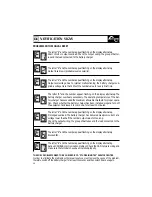
BATTERY CHARGER PROGRAMMING
The devices belonging to one group “ ”, “ ” or “ ” can only dialog between themselves.
Group “ ” (Universal) is an exception as this can dialog with any other device.
The distinction between different groups is very important in order to connect all the devices to
the same CAN network even if they belong to different electrical systems.
The letter “ ” , “ ” or “ ”, will appear flashing on the display according to the current setting.
To change the setting, press the key quickly ( press and release the key in less than 1
second).
To make the setting operative press the key for at least 2 seconds. The display will confirm the
setting by showing the letter selected for one second (steady).
SELECTING GROUP ORDER OF PRIORITY
This function is used to determine the priority level of the battery charger within the network
group. At the moment this function is not used by the battery charger (it is reserved for future ex-
pansions).
The number “ ” , “ ” or “ ” will appear flashing on the display according to the current set-
ting.
To change the setting press the key quickly (press and release the key in less than 1 sec-
ond).
To make the setting operative press the key for at least 2 seconds. The display will confirm the
setting by showing the number selected for one second (steady).
Once the programming procedure has been completed, the following symbol will be shown for
1 second: “ “.
ACTIVATING/INACTIVATING THE MONITOR MODE
This function enables the user to activate or inactivate the battery charger’s “monitor” mode.
If it is activated, the “monitor” mode enables the battery charger to transmit and receive data
on the CAN network even if no AC power is being delivered. To do this, the battery charger is
supplied with power from the group of batteries using the master output. The current absorp-
tion, with “monitor” mode active, is less than 75mA (120mA for 24V models).
The battery charger exits “monitor” mode (is turned off) if the voltage of the master group of
batteries is less than 7Vdc (14Vdc for the 24V models).
This mode should be activated when the remote terminals are connected to the CAN network.
The letter “ ” (monitor mode Off) or “ ” (monitor mode On [Stand-by]), will appear flashing
on the display according to the current setting.
To change the setting press the key quickly (press and release in less than 1 second).
To make the setting operative press the key for at least 2 seconds. The display will confirm the
setting by showing the letter selected for one second (steady).
Summary of Contents for Innotec MBC 12-25/3
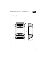
Page 13: ...205 181 90 135 155 75 MBC BATTERY CHARGER DIMENSIONS mm 12 08 2 12 12 2 11 ...
Page 14: ...12 268 244 90 135 155 75 MBC BATTERY CHARGER DIMENSIONS mm 12 25 3 24 12 2 ...
Page 29: ...280 334 272 220 127 MBC BATTERY CHARGER DIMENSIONS mm 12 30 3 12 40 3 27 ...
Page 30: ...28 358 412 272 220 127 MBC BATTERY CHARGER DIMENSIONS mm 12 60 3 24 30 3 ...
Page 45: ...447 495 272 220 127 12 80 3 24 60 3 24 80 3 43 MBC BATTERY CHARGER DIMENSIONS mm ...


