Installation and connection
5.2
Installing with foundation
NOTE
Material damage due to distortion of base plate.
Position the base plate as follows on the foundation and
attach.
5.2.1
Place pump unit on the foundation
Aids, tools, materials:
–
Anchor bolts (
→
installation drawing)
–
Steel shims
–
Mortar casting compound, no shrinkage
–
Spirit level
1. Lifting the pump unit
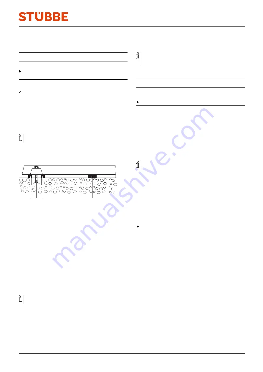
2. Hook anchor bolts in the mounting holes on the base plate
from below.
Observe manufacturers information when using the fixing
material.
3. Position the pump unit on the foundation. When doing so
lower the anchor bolts into the prepared anchoring holes.
3
2
1
2
Fig. 5
Installation with foundation
4. Align the pump for height and system dimensions using
steel shims as follows:
–
Arrange steel shims (2) to the left and right of each
anchor bolt (1).
–
If the distance between the anchoring holes is
> 750 mm, then arrange additional steel shims (3) on
each side of the base plate in the center.
5. Ensure that the base plate lies flat against steel shims.
6. Check the permissible height deviation (1mm/m) using a
mechanical spirit level in a longitudinal and a transverse
direction
7. Repeat the procedure until the base plate is correctly
aligned.
5.2.2
Attaching pump unit
Filling the base plate with mortar casting compound
improves dampening properties.
1. Fill the anchoring holes with mortar casting compound.
2. When the mortar casting compound has set, bolt the base
plate at three points to the specified tightening torque.
3. Before tightening the remaining bolts, arrange shims next
to every bolt to even out any irregularities in the mounting
surface.
5.3
Planning pipelines
Water hammer may damage the pump or the system. Plan
the pipes and fittings as far as possible to prevent water
hammer occurring.
5.3.1
Specifying supports and flange connections
NOTE
Material damage due to excessive forces and torques on
the pump.
Ensure pipe connection without stress.
1. Plan pipes safely:
–
No pulling or thrusting forces
–
No bending moments
–
Adjust for changes in length due to temperature
changes (compensators, expansion shanks)
2. Support pipes in front of the pump.
3. Ensure the pipe supports have permanent low-friction
properties and do not seize up due to corrosion.
5.3.2
Specifying nominal widths
Keep the flow resistance in the pipes as low as possible.
1. Ensure nominal suction pipe width is not smaller than the
nominal suction flange width.
–
Recommended flow velocity < 1 m/s
–
Maximum flow velocity = 9 m/s
2. Ensure the nominal pressure line width is not smaller than
the nominal discharge flange width.
–
Recommended flow velocity < 3 m/s
–
Maximum flow velocity = 12 m/s
5.3.3
Designing pipelines
Plan pipes safely:
–
No pulling or thrusting forces
–
No bending moments
–
Adjust for changes in length due to temperature
changes (compensators, expansion shanks)
300 092
BA-2018.08.21 EN
SHM
15


