


DE-STA-CO
Subject to technical modifications without notice
15.13
S
tr
o
n
g
H
o
ld
C
la
m
p
in
g
S
y
s
te
m
T
M
Example: Boring a hole in alloy steel heat treated to 37 Rc (unit power
1.7), with a depth of cut of .060", a feed rate of .003" inches per
revolution gives a result of:
.060 x .003 X 1.7 x 396,000 = 121 lbs. Cutting Force
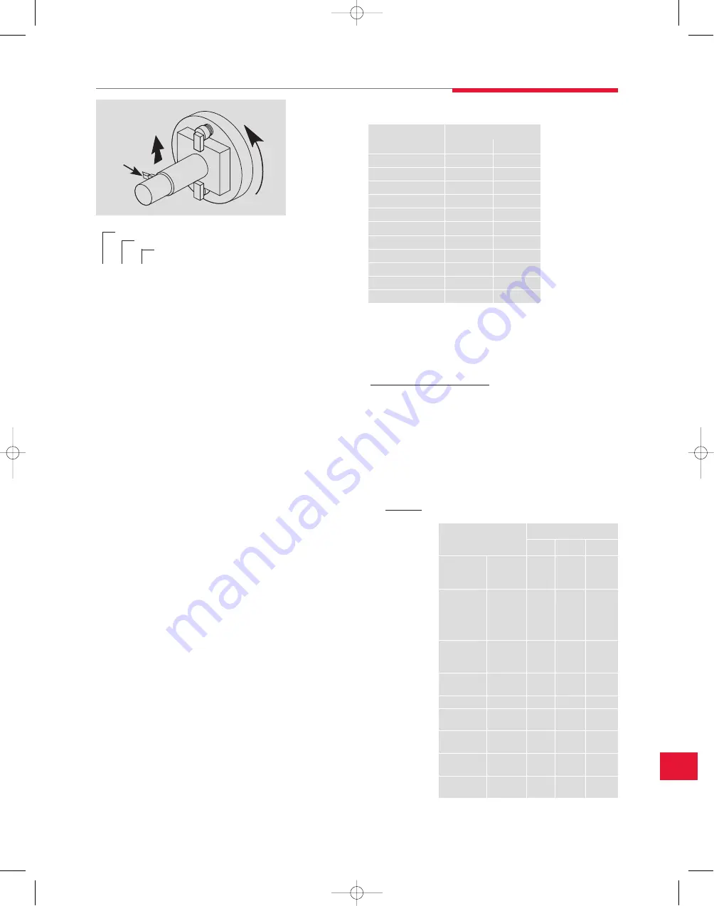
Drilling
The forces involved in drilling can be separated into two distinctly
different categories: thrust and torque. With the number of drill styles
available, the thrust varies tremendously. Torque is somewhat less
variable and can be estimated as shown:
Feed (IPR) x (Drill Dia.)
2
x Unit Power x 49,500 =
Drilling Torque (In. Lbs.)
For example, drilling a 3⁄4” diameter hole in magnesium (unit power .2)
with a feed rate of .010” per revolution gives a result of:
.010 x .75
2
x .2 x 49,500 = 56 in. lbs.
Friction Coefficient
Now that an estimate of the amount of cutter force being transferred to
the workpiece is available, we must determine how much clamping
force is necessary to resist the cutter force. This depends on the
amount of friction between the workpiece and the fixture, commonly
referred to as the friction coefficient.
Typically, if an object is lying on a surface, the amount of force required
to slide it sideways will be considerably less than the weight of the
object. It follows then that when clamping a workpiece to resist
machining forces, the clamping force will need to be much higher than
the machining force. The following chart shows approximate
friction coefficients:
The estimated clamping force is divided by the appropriate friction
coefficient and then multiplied by a suitable safety factor to get an
estimated total clamping force required.
Example: A steel workpiece on steel rest buttons is being machined
using coolant. The estimated machining force is 300 lbs. From the table
the friction coefficient for steel on steel (lubricated) is .16. After
choosing an appropriate safety factor (usually about 2), the estimated
total clamping force would be:
This total clamping
force may now be
divided
by
the
number of clamps
holding
the
workpiece, which
equals the clamping
force needed for
each clamp.
Depth of Cut (in.)
Feed per Revolution (in.)
Unit Power
____X____X____X 396,000 = _____ lbs.
Cutting Force
Force
Cutting
Tool
Static Friction Coefficients
for Steel on Various Materials
Machining Force (lbs.)
Friction Coefficient
x Safety Factor = Total
Clamping
Force (Lbs.)
300
.16
x 2 = 3750 lbs. Total Clamping Forces
System design information
TABLE A
Unit Power hp/in
3
/min
Turning
Drilling
Milling
Material
Hardness
Bhn
HSS &
Carbide
Tools
HSS
Drills
HSS &
Carbide
Tools
STEELS
Plain
Carbon
Alloy Steels
85-200
35-40Rc
40-50Rc
50-55Rc
55-58Rc
1.4
1.7
1.9
2.5
4.2
1.3
1.7
2.1
2.6
3.2
1.4
1.9
2.2
2.6
3.2
CAST IRONS
Gray, Ductile
& Malleable
110-190
190-320
0.9
1.7
1.2
2.0
0.8
1.4
STAINLESS
STEELS
135-275
30-45Rc
1.6
1.7
1.4
1.5
1.7
1.9
TITANIUM
250-375
1.5
1.4
1.4
NICKEL
ALLOYS
80-360
2.5
2.2
2.4
ALUMINUM
ALLOYS
30-150
500 kg
0.3
0.2
0.4
MAGNESIUM
ALLOYS
40-90
500 kg
0.2
0.2
0.2
COPPER
ALLOYS
10-80Rb
80-100Rb
0.8
1.2
0.6
1.0
0.8
1.2
Material
Friction Coefficient
Clean
Lubricated
Brass
0.35
0.19
Bronze
–
0.16
Bronze, Aluminum
0.45
–
Bronze, Phosphor
0.35
–
Bronze, Sintered
–
0.13
Carbon, Hard
0.14
0.11-0.14
Copper-Lead Alloy
0.22
–
Graphite
0.10
0.10
Iron, Cast
0.40
0.21
Steel
0.80
0.16
Tungsten Carbide
0.4-0.6
0.1-0.2
15_StrongHold.qxp:15_DES_StrongHold-1-14.indd 1/2/08 9:03 AM Page 15.13


