


DE-STA-CO
Subject to technical modifications without notice
15.11
S
tr
o
n
g
H
o
ld
C
la
m
p
in
g
S
y
s
te
m
T
M
Torque vs. Tension
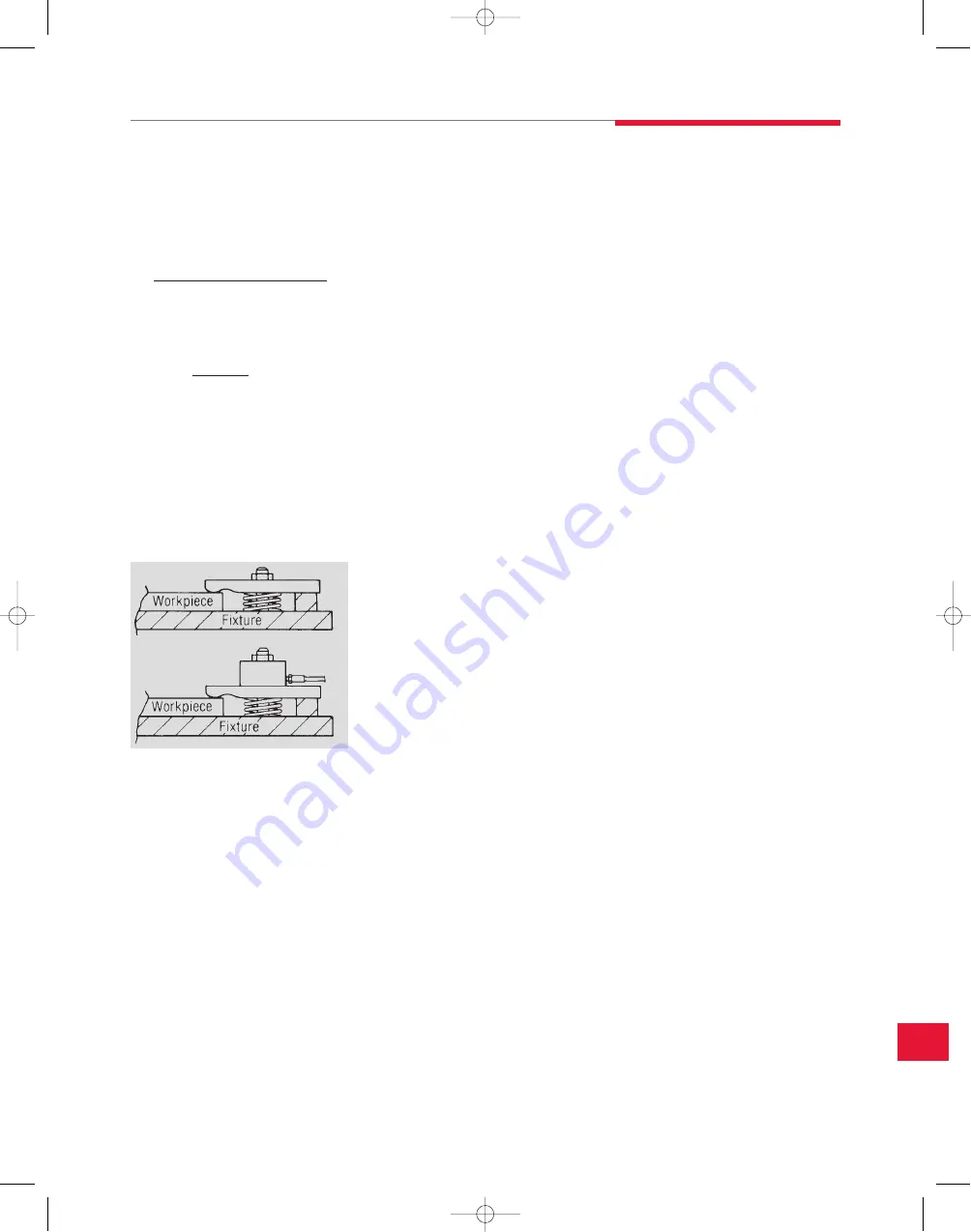
A user’s first introduction to hydraulic power workholding is often
the replacement of the nut on a typical strap clamp with a center
hole cylinder.
If the torque of the nut is known, the resulting tension on the bolt or
stud can be easily approximated.
For example, a 1⁄2-13 UNC nut is torqued to 300-in. lbs. The resulting
approximate tension would be:
The most accurate way to determine that the hydraulic power clamping
system is exactly duplicating the mechanical system is to place the
center hole cylinder over the stud or bolt and replace the nut loosely
over the cylinder. Use the hydraulic system to partially extend the
cylinder until it contacts the nut. Use a torque wrench to torque the nut
to its original value while monitoring the system pressure gauge. When
the nut is properly torqued, the gauge will indicate the exact system
pressure setting for this application.
Operating Pressures
Most DE-STA-CO workholding components are rated at 5,000 PSI.
When designing, it is a good rule of thumb to choose components for
your fixture that will give you the forces you need at a pressure of about
3,000 PSI. This gives you plenty of latitude to adjust the system
pressure both up and down when fine tuning the fixture on the machine
tool. Operating at lower pressures, while sometimes necessary, does
not make the most efficient use of these components. Higher pressures
allow the use of smaller components, saving cost and fixture space.
Design Stroke Length
Clamps and cylinders should never be designed into a fixture at their
rated full stroke. Always use something less than full stroke to make
sure that all tolerances and variations in the workpiece, workholding
device and fixture can be accepted, insuring that the workpiece is
properly clamped.
Volume Calculations
The total volume required to actuate a circuit should be checked to
make sure that the power source chosen has enough usable fluid
capacity. The fluid volume required to fully actuate each clamp and
cylinder is listed in the charts on each product page throughout the
catalog. By totaling this value for each component, you know the
maximum fluid volume that could possibly be used in this fixture. Even
the smallest DE-STA-CO pumps have enough fluid volume for most
applications.
Since the fixture is designed to use less than the full stroke of the
actuators, the actual fluid volume will be less. If it becomes necessary
to get an exact figure, it can be easily calculated using the
following formula:
Effective Area (sq. in.) X Stroke (in.)
= Fluid Capacity (cu. in.)
The effective area of the actuators (from product chart) multiplied by
the stroke used (not total stroke) will result in the fluid volume.
For example, if a cylinder has an effective area of 2 square inches, and
an actual stroke of 3 inches, its fluid volume will be 2 x 3 or 6 cubic
inches. (For easy reference, 231 cubic inches = 1 gallon.)
System Care and Maintenance
The single most important factor in determining the life of a properly
designed system is the effort taken to keep the fluid clean.
System Flushing
During assembly, make sure all fluid-carrying components are flushed
with clean solvent and blown dry. Hydraulic tubing is particularly
notorious for the amount of contaminants found inside. If not removed,
this debris will quickly damage seals and score precision-fit metal
parts. The contamination will also clog passages in pumps and
control valves.
After fixture assembly, the entire system should be flushed to remove
any contamination created during assembly. Use only hydraulic fluid for
this procedure. Solvents may become trapped in the system,
contaminating the fluid.
Once the fluid in the system is clean, be sure to keep it that way by
changing the fluid on a regular basis and making sure that extreme
care is taken whenever the system is disconnected or disassembled so
that new contaminants are not introduced.
Torque (In. Lbs.)
Nominal thd. size (In.) X .12
= Tension (Lbs.)
From this:
To this:
= 5,000 lbs. Tension
300
.5 x .12
System design information
15_StrongHold.qxp:15_DES_StrongHold-1-14.indd 1/2/08 9:03 AM Page 15.11


