TROUBLESHOOTING
POWER LINE PROBLEMS
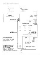
PRIMARY POWER (AC source) problems are most commonly (a) complete loss of AC power,
or (b) phase loss, in which one phase loses power.
a) Check line safety switch (ON). Check fuses or breakers in supply line. Using an AC
voltmeter, measure input power at contactor terminals L1, L2, L3.
b) When power is lost on one phase, the current ripple will increase and trip the AC line circuit
breaker (at the wall, or in a Console Distribution Panel). To detect a lost phase, measure the AC
voltage phase-to-phase at contactor input terminals L1, L2, and L3.
PROBLEMS of this nature, once detected, are generally corrected by the power supplier
(i.e. the local utility company).
BOOST CIRCUIT PROBLEMS
THE BOOST CIRCUIT generates the high open circuit (no load) DC voltage which, in
conjunction with the igniter pulse, will ignite the xenon bulb. The open circuit voltage should
measure at least 110 V.DC. It is displayed briefly on the lamphouse ammeter by pressing the VOLT-
AGE button at ignition, or the reading can be sustained by disabling lamphouse ignition by removing
one AC lead from the igniter feed (Strong lamphouse: 5 or 6).
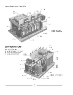
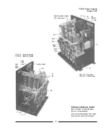
A TERTIARY WINDING on the main transformer (T1) supplies the source for the Boost
Circuit. Three wires derive from the T1 transformer; two are single conductors, and the third is a
soldered pair. The Boost Circuit should be connected only to the (2) single conductors. Filter
capacitors C1 & C2 store energy and also contribute to bulb ignition.
CONTROL CIRCUITRY
THE MAIN POWER TRANSFORMER is energized by contactor K1, which is pulled by (a)
an automation system closure or (b) manual actuation of the lamphouse ON switch. All lamphouse
interlock switches (Door, Air, etc.) must also be closed to complete the contactor circuit.
ANY INTERRUPTION of the control circuit will disable K1 and open the AC circuit to the
rectifier. In addition to the above lamphouse interlock switches, thermal switch S1, mounted to the
rectifier heat sink, will open and disable K1 if the temperature at the heat sinks exceeds 190° F. (88°
C.). The S1 switch will automatically re-set when temperatures fall to safe levels.
STEPDOWN TRANSFORMER T2 is protected by a (3) Ampere in-line fuse F1. In the
event of a failure of a lamphouse control component (blower, igniter, etc.), the fuse will open. This,
in turn, will disable the lamphouse control circuit and cause the power supply contactor K1 to open.
Repair or replace the faulty lamphouse component before replacing the fuse (3 A. Std.);
do not
overfuse.
WARNING: Exercise extreme caution when taking
voltage measurements in a power ON condition.
Allow the capacitors (2) minutes to discharge.
7
Summary of Contents for XENON FXPS
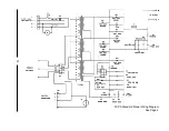
Page 12: ...FXPS Standard Model Wiring Diagram See Page 4 10 ...
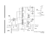
Page 13: ...FXPS Model LB Wiring Diagram See Page 5 11 ...
Page 18: ......


