background image


5


BA_170-22D_A14_180704_en


Every person in charge of setting up, operating, servicing and repairing the 
machine must first read and understand the operating instructions and 
particularly the safety instructions before starting up the machine. 

General notes on safety 

Failure to comply with the following safety instructions can lead to bodily 
injury or damage to the machine. 

1. 

The machine must only be operated by persons familiar with the relevant 
operating instructions and who have been instructed accordingly. 

2. 

Before commissioning also read the notes on safety and the operating 
instructions of the sewing drive manufacturer. 

3. 

Only use the machine in the intended manner and never without the 
provided guards. Always observe the pertinent safety regulations. 

4. 

Switch off the main switch or pull the power plug for threading, changing 
the reels, exchanging sewing tools such as needle, gripper, needle plate, 
transport devices, possibly cutter and cutting block, for cleaning and when 
leaving the workplace as well as for maintenance. 

5. 

General maintenance tasks may be carried out only by properly trained 
persons in accordance with the operating instructions. 

6. 

Repair work, retrofitting and maintenance may be carried out only by 
technicians or specially trained personnel. 

7. 

When servicing or repairing pneumatic equipment, the machine must be 
disconnected from the pneumatic supply. Exceptions are only allowed for 
adjustment work and tests of functionality performed by specially trained 
technicians. 

8. 

Only specially qualified technicians may work on the electrical equipment. 

9. 

It is forbidden to work on electrically live components! Exemptions are 
covered by the EN50110 (DIN VDE0105) regulations. 

10.  Any retrofitting or alterations to the machine may only be performed under 

strict compliance with all pertinent safety regulations. 

11.  Only use our approved spare parts when servicing and/or repairing the 

machine. 

12.  It is forbidden to operate the sewing head until it is determined that the 

entire sewing unit complies with EU provisions. 

13.  It is essential that you observe and follow these instructions as well as the 

generally valid safety regulations. 

Summary of Contents for 170-22D

Page 1: ...For the professional user Für den professionellen Anwender Betriebsanleitung Class Klasse Model Ausführung Dated Stand 170 22D 14 Operating Instructions Spezialmaschinen GmbH ...

Page 2: ...reates trust trust in our technology our service and not least of all in our good name ie finden die Strobel Schutzmarke auf jeder Strobel Maschine die unser Werk verlässt Und das aus gutem Grund Denn dieses Zeichen garantiert Ihnen die hohe Qualität unserer Produkte Qualität die Vertrauen schafft in unsere Technik unseren Service und nicht zuletzt in unseren guten Namen S Y The sign of quality ...

Page 3: ...this reason we kindly request that you read the operating instructions closely It provides all the information you need for trouble free operation And if you do happen to need a spare part the enclosed spare parts list gives a complete overview It is clearly classified according to components so that you can find the required part quickly and easily In order to avoid errors we request you to quote...

Page 4: ......

Page 5: ...1 BA_170 22D_A14_180704_en ...

Page 6: ...2 BA_170 22D_A14_180704_en ...

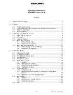
Page 7: ... toothed belt 14 3 5 1 Tensioning the toothed belt Fig 5 14 3 5 2 Positions of the machine 15 4 Instructions for use 16 4 1 Needles and threads 16 4 2 Inserting the needle 16 4 3 Threading and thread course 17 4 4 Thread tension 17 4 5 Thread take up lever 17 4 6 Stitch depth regulator 18 4 6 1 General 18 4 6 2 Setting the stitch depth 18 4 6 3 Digital stitch depth indication 18 4 6 4 Changing the...

Page 8: ...indstitch hemming 26 5 4 2 Attaching the trouser waistband lining Fig 13 27 5 4 3 Attaching facings 28 5 5 Problems during sewing and possible solutions 29 6 Machine maintenance 32 6 1 General 32 7 Variable sewing tools 32 8 Optional extras 35 8 1 Thread trimmer 35 8 2 Pneumatic lifting 35 8 3 Compact drive 35 8 4 Stand set 35 Subject to change without prior notice ...

Page 9: ...nd when leaving the workplace as well as for maintenance 5 General maintenance tasks may be carried out only by properly trained persons in accordance with the operating instructions 6 Repair work retrofitting and maintenance may be carried out only by technicians or specially trained personnel 7 When servicing or repairing pneumatic equipment the machine must be disconnected from the pneumatic su...

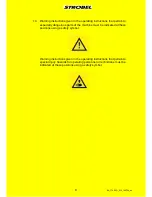
Page 10: ...n to especially dangerous parts of the machine must be indicated at these positions using a safety symbol Warning instructions given in the operating instructions that pertain to special injury hazards for operating personnel or technicians must be indicated at these positions using a safety symbol ...

Page 11: ...r side of the housing Class identification serial number and orientation of the machine 2 3 The class 170 22 is for the manual looping of the lining the pocket bag and the trimming on coats and jackets as well as for hemming trousers Range of applications Due to the spring suspended plungers the machine manage alterations in the sewing matter position such as cross seams belt loops waist tucks or ...

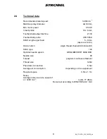
Page 12: ...h upper feed 5 8 mm depend on fabric Kind of stitch single thread chain stitch blind stitch Stitch type 103 Optional needle system GROZ BECKERT 4669 EEO Needle size 80 Thread polyester continuous filament Thread size 120 2 Pneumatic connection 6 bar Average air consumption depending on the equipement Required space 0 5m x 1 1m Noise Average noise level at a speed of n 3200 min 1 LpAm 77 dB A Noise...

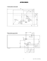
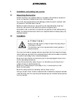
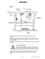
Page 13: ... injuries or finger bruises through pulling in of garments or hairs The machine may not be operated without belt guards for head and motor If the machine head is supplied without stand and motor first make the borings into the table top as shown in the drawing Mount rods and treadles and electric connections according to the connecting diagram Mount the motor Electric connection as per connecting ...

Page 14: ... must be tightened firmly Check positions according to point 3 4 2 Positions of the machine and adjust if necessary A T T E N T I O N Before putting the machine into service make sure that the electric connecting data on the motor s name plate mainly voltage and frequency correspond to your electric network All rust protection agents such as Vaseline and similar agents have to be wiped off careful...

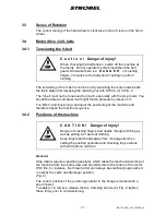
Page 15: ...mb pressure by about 2 cm Too little V belt tensioning can impair the positioning of the machine and therefore impair the function sequence 3 4 2 Positions of the machine C A U T I O N Danger of injury Danger of crushing fingers and needle through stitching as well as pulling in of parts of clothing Keep fingers and hands away from moving parts when setting the position generator and checking the ...

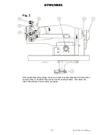
Page 16: ...180704_en Fig 2 With positioning with plunger reset the motor reverses after thread cutting for a certain value to facilitate the insertion of the sewing matter This does not affect the setting of the position generator ...

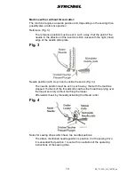
Page 17: ...slide plate Fig 3 Needle position with stop in and outside the seam Fig 4 The needle position must be set in such a way that with the machine stopped the hook of the thread knife catches the thread loop lying over the looper securely without touching the looper Afterwards check by manually activating the thread cutter Fig 4 Notes for sewing drives which have two needle positions The above mentione...

Page 18: ...belt should not be tensioned too much You should be able to compress it with light thumb pressure by about 5 mm Too little or too tight toothed belt tensioning can impair the positioning of the machine and therefore impair the function sequence Tensioning the toothed belt Fig 5 Release the upper and the bottom retaining screw 1 2 at the upper part of the machine Pull out the motor slightly and tig...

Page 19: ...nce position must be set in such a way that the point of the needle in direction of the insertion stitch closes with the right inner edge of the needle slide plate Needle position with stop in and outside the seam Fig 4 The needle position must be set in such a way that with the machine stopped the thread knife catches the thread loop lying over the looper securely without touching the looper Afte...

Page 20: ... respectively Because of their high strength and ability to slide combined with a low volume they are to be preferred over a spun thread G u a r a n t e e d r e m a r k This machine has been set and sewn off with genuine GROZ BECKERT needles No guarantee can be granted if the settings are modified for using different needle types 4 2 Inserting the needle A T T E N T I O N Danger of body injuries S...

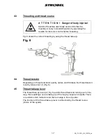
Page 21: ...using the thread take up Fig 6 4 4 Depending on thread and fabric quality nature and thickness the thread tension is set by tension nut 1 Thread tension Fig 6 4 5 The thread take up lever 2 Thread take up lever Fig 6 avoids thread twist and turning over of the loop thus enabling a secure taking up of the loop by looper and needle There is a uniform stitch formation and the hem edge is free of puck...

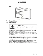
Page 22: ... 3 On the stitch depth display Digital stitch depth indication Fig 7 the immersion height can be read off digitally With frequently changing sewing matter thickness this makes the finding of earlier settings substantially easier Current supply is through a 9V battery located in the housing To prevent premature discharging of the battery the display should be switched off with the toggle switch on ...

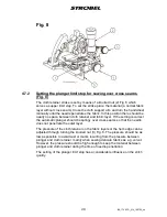
Page 23: ...e lock tooth is combined with a regulator screw 2 which limits the lock tooth lift off in upward direction Fig 8 This combination is described as plunger stop Plunger stop and spring suspended plunger prevent that the external layers of the sewing matter are stitched into during the sewing of cross seams and other thickenings and that undesired markings become visible The locking tooth is screwed ...

Page 24: ...r If the setting is correct the automatic plunger should be springy over cross seams so that the needle does not penetrate the outer layer The pressure of the cloth retainer on the fabric layers or the hem edge can be adjusted through turning the knurled nut 3 Fig 8 The pressure should be as low as possible to avoid twist or marks resulting from the pressure between plunger and cloth retainer main...

Page 25: ...er spring pressure up or down This is carried out by altering the pretension of the tension spring 2 Setting the automatic plunger Fig 9 Fig 9 with the adjusting screw 3 which can be reached easiest from the back of the fabric carrier arm Always valid larger plunger resistance turn screw 3 to the right smaller plunger resistance turn screw 3 to the left Fig 9 ...

Page 26: ...ng knob pressed and turn the handwheel to the front until the desired stitch length catches 4 8 3 After loosening the two fastening screws the feed dog can be adjusted in relation to the needle plate If the stitch length is modified considerably e g from 8 to 5 the feed dog should be re adjusted as well Setting the feed dog Also when the fabric thickness or quality changes it is recommended to re ...

Page 27: ...ne A needle positioning motor is needed for an exact machine positioning and to operate the electromechanical thread trimmer and pneumatic lifting Please observe the operating instructions of the sewing drive supplied with the machine where you will find instructions to program the control and the motor speed ...

Page 28: ...nd removing the fabric sewing process By pressing the left hand treadle the cloth support arm is lifted Place material under the needle plate and leave the left hand treadle The machine starts sewing by operating the right hand treadle The machine runs at maximum speed when the right hand treadle is completely pressed down see 4 9 Motor b Pneumatic lifting optional extra Fig 5 shows the treadle s ...

Page 29: ...25 BA_170 22D_A14_180704_en Fig 10 ...

Page 30: ...lacing the material guide 5 to get the corresponding limit stop for the hem edge You can sew at the hem edge or on the hem See Fig 12 6 check the stitch length and readjust the feed dog if necessary 7 Set the thread tension The seam should lay loosely on the hem 8 Re thread to obtain a better seam appearance Place the material and make sure that the feed dog can catch the beginning of the seam aft...

Page 31: ...have to be sewn Also the rounded off plunger is recommended for this operation point Attaching the trouser waistband lining Fig 13 7 Variable sewing tools to avoid marks at the outer fabric side Recommended needle sizes 80 90 There are two different types of operations Fig 13a and b a sewing the waistband on the lining b sewing the waistband on the edge ...

Page 32: ...28 BA_170 22D_A14_180704_en Fig 13 a b 5 4 3 This operation is shown in Attaching facings Fig 14 Fig 14 ...

Page 33: ...spond to needle size thread is too thick Solutions replace or polish the damaged parts re adjust looper and or loop stroke re adjust thread tension check thread course choose the correct thread size Please observe thread course thread needle plate with plunger and cloth retainer needle and thread tension should always be set and chosen according to the material to be sewn Inexact needle penetratio...

Page 34: ...ssible reasons thread trimmer not in final position microswitch locks control error mechanical damage machine blocks Solutions switch machine off and on again check the knives cutting position check the programming eliminate mechanical problem call service if necessary The fabric is marked or damaged Possible reasons unsuitable feed dog teeth plunger shape unsuitable for the fabric to be sewn pres...

Page 35: ... are caught by the feed dog unintended stitch length modification spring loaded plunger blocks in the cross seam area Solutions check feed dog setting and stitch length replace feed dog if necessary set material support pressure correctly check if lower side of needle plate feed or sewing parts are damaged and replace or repolish them if necessary choose correct needle plate for thicker materials ...

Page 36: ...ings General Release the machine head s slotted pan head screw and remove cover to lubricate looper link and the screw Clean all movable parts regularly from fabric fibres 7 Variable sewing tools A T T E N T I O N Switch off machine electrically and confirm that the machine is really in standstill position by operating the treadle for the motor control Otherwise danger of finger bruises and needle...

Page 37: ...le plate Standard 6 0 mm opening 480 0254 Optional 4 5 mm opening 480 0256 Cloth retainer Optional 288 0216 Standard 288 0215 Optional 288 0214 Standard 288 0213 included in 480 0256 Stitch formation Feed dog Standard 182 0301 Optional 182 0305 ...

Page 38: ...0 22D_A14_180704_en Cl 170 22 Needle plate Optional 7 0 mm opening 480 0257 Cloth retainer Optional 288 0225 Standard 288 0217 included in 480 0257 Stitch formation Feed dog Standard 182 0301 Optional 182 0305 ...

Page 39: ... machine or as separate kits Optional extras 8 1 798 0496 electromechanical thread trimmer Prerequisite here is use of the EFKA Kompakt DC 1500 Thread trimmer 8 2 The use of a pneumatic lifting is only recommended if the machine is equipped with a needle positioning motor Pneumatic lifting 8 3 8 4 Compact drive Stand set ...

Page 40: ......
Page 41: ...stichmaschinen For the clothing industry Single and two thread high performance hemming machines Bluff edge hemming machines Two thread blind stitch felling machines Roll and flat padding machines Automatic lapel padding machine and other special sewing machines For the shoe industry Single thread overseaming ma chines with and without differen tial feed Für Kürschnereien und Pelzkonfektion Pelzsc...

Page 42: ...n unserem Ausstellungsraum live erleben Wir freuen uns auf Sie Then phone write or simply come and see us You can have further information about our products at any time or experience the Strobel machines live in our show room We re looking forward to meeting you Spezialmaschinen GmbH Postfach 1242 82168 Puchheim Siemensstraße 3 82178 Puchheim DEUTSCHLAND www strobel biz Telefon 49 89 80096 0 Tele...

Reviews: