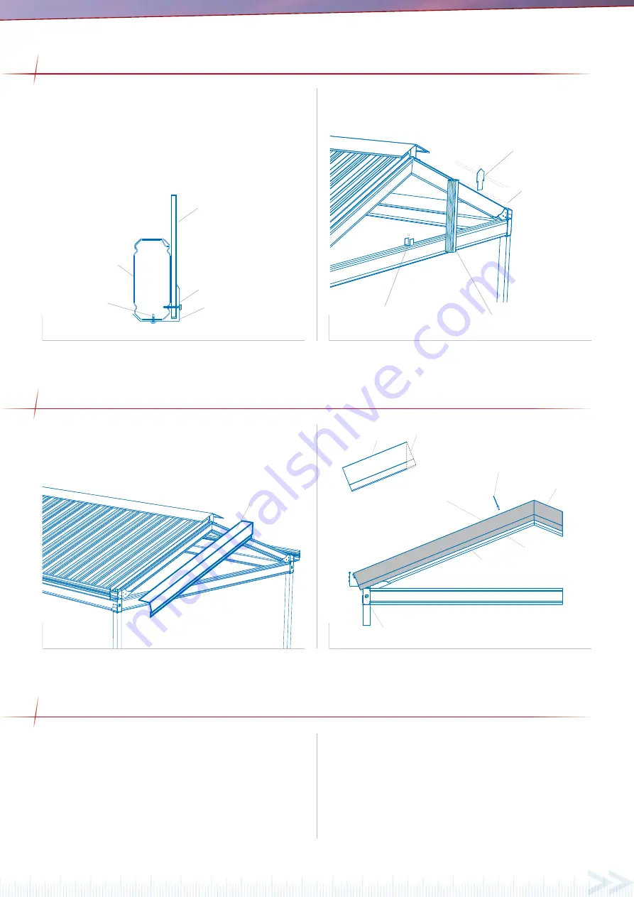
Figure 23.0
Figure 23.1
Gable infill panels are to be cut in triangle shapes to fit the end
frame. Panels can be painted to the desired colour before installing.
End struts are fixed mid-span of the header to a header beam
bracket at the base and an end strut plate at the ridge. Infill panels
are fixed through the top groove of rafters and the lower groove of
the header beam with 8x35mm self embedding self drillingt screws
at 500mm centres. Panels are fixed to the end strut at the same
spacings. Attach the header flashing to the underside of the header
beam with 12x20 hex head screws to neatly finish the base of the
infill panels. Refer figure 23.0 and 23.1.
infill panel
8x35 self embedding screws
header flashing
12 x 20 hex head
self drilling screws
header beam
fix bracket to header wiith
two 12x20 hex head self
drilling screws
fix to strut with two
12x20 hex head self
drilling screws either
side
fix to front of ridge with
two 12x20 hex head self
drilling screws
fix strut to bracket with two 12x20 hex
head self drilling screws on either sides
Fixing into the Concrete Footing
Thoroughly check the posts with a spirit level. When plumb, fill the
post hole with approximately 150mm of concrete and use a shovel
or pole to agitate the concrete to remove any air pockets. Repeat
this process until the hole is full, continually checking the posts
as you go. The concrete must have a slight slope that runs away
from the column to ensure any water does not pool around the
base (figure 25.0). Once the concrete is set remove any temporary
bracing or props.
Fixing onto Existing Concrete: External Footing
If the columns are to be fixed to an existing concrete slab with an
external footing plate, each plate must be fixed to the concrete. For
a 68 Outback Column refer figure 25.1, for a reinforced 68 Outback
column refer 25.3 and for an SHS column refer figure 25.2. The
minimum distances from an anchor hole to the concrete edge is
70mm for M10 anchors, 75mm for M12 anchors and 120mm for
M16 anchors.
FINAL FIXING
Attach the barge cap by screwing the lower lip to the gable rafter
and rivet the top section to the deck as shown in figure 24.1. Mitre
the barge at the apex of the gable for a neat finish. Trim the barge
at the gutter end to ensure a neat finish.
Figure 24.0
Figure 24.1
ATTACHING BARGE CAPPING
barge cap
barge cap
mitre end
mitred barge cap
gable rafter
mitred barge cap
fr
on
t gut
ter
gut
ter st
rap
gut
ter
riv
et
ed
to cutback
flashing and
top sheet
eiving channel
4.8mm sealed
riv
ets
rivet barge cap to crest of
decking at 500mm centres
trim barge cap
for neat finish
fix barge cap to gable rafter
at front using 12x20 hex
head self drilling screws


