background image

4

Introduction

StorCase Technology, Inc.

InfoStation 14-Bay FC User's Guide - Rev. B00

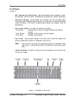
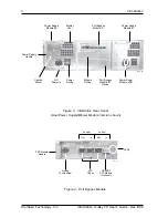
Front Panel

(Figure 2)

•

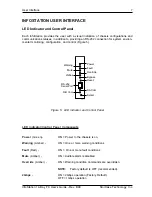
LED  Indicator and Control Panel

 - LED panel displays system statuses, alarms,

and warnings.  Refer to section "

InfoStation User Interface

" for further information.

•

SCA  Drive  Carrier(s) 

-  Accommodate  up  to  fourteen  (14)  3.5"  low-profile  Fibre

Channel devices.  Backplane design with direct-connect SCA connectors eliminates

cable  connections  to  FC  drives,  increases  data  integrity,  and  supports  drive  hot

swappability.

•

Drive  Carrier  LED(s)

  -  Provides  the  following  information:

Drive Ready

 -

Indicates that the drive is properly installed and ready for

access.

Drive  Activity

  -

Indicates that the drive is being accessed.

Drive Fault

  -

Indicates a drive failure.

•

Key  Lock(s)  - 

Assure  proper  seating  of  the  drive  carrier  within  the  chassis  and

prevent unauthorized removal or installation of the carrier.

NOTE:

The key lock is 

only

 to prevent unauthorized removal or installation of the

drive carrier.  Locking the key lock is not requried for drive carrier oper-

ation.

•

Chassis Handle(s) - 

Provide a sturdy grip for the installation and removal of the

rack-mount  chassis.

Figure 2:  InfoStation Front Panel

Chassis

Handle

SCA Drive

Carrier

Drive Carrier

Handle

Key

Lock

Drive Carrier

LEDs

LED Indicator and

Control Panel

14FC_02

RS-232

Serial Port

Summary of Contents for InfoStation

Page 1: ...StorCase Technology InfoStation 14 Bay 2Gbps Fibre Channel External Expansion Chassis User s Guide...

Page 2: ...nology Inc StorCase Technology Inc 17600 Newhope Street Fountain Valley CA 92708 9885 Phone 714 438 1850 Fax 714 438 1847 StorCase Technology InfoStation 14 Bay 2Gbps Fibre Channel External Expansion...

Page 3: ...ears excepting the RAID controller power supply fan and blower components which are covered by the three year warranty described below Three Year Warranty The following StorCase products are covered b...

Page 4: ...932 738900 Disclaimers The foregoing is the complete warranty for the products identified above and supersedes all other warranties and representations whether oral or written StorCase expressly discl...

Page 5: ...ase Technology Inc 17600 Newhope Street Fountain Valley CA 92708 17600 Newhope Street Fountain Valley CA 92708 InfoStation 14 Bay Fibre Channel S10D106 S10D111 ITEEmission EN 55022 1998 EN 61000 3 2 H...

Page 6: ...er available consult your dealer or local power company 6 Do not attempt to service this product yourself as opening or removing covers may expose you to dangerous voltage points or other risk Refer a...

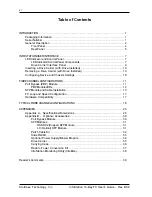
Page 7: ...guring Device and Chassis Settings 10 FIBRECHANNELCONFIGURATIONS 11 Port Bypass PBP Module 11 PBPModuleLEDs 12 SFP Module and Cable Installation 13 FC Loop and Speed Configuration 17 Hardware Compatib...

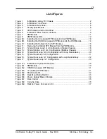
Page 8: ...ing the Optical SFP Module from the PBP Module 16 Figure 12 Typical Single Loop 1x14 Configuration Single Chassis 18 Figure 13 Typical Single Loop 1x14 Configuration Multiple Chassis 19 Figure 14 Typi...

Page 9: ...ensure accuracy of this document Storcase Technol ogy Inc assumes no liability resulting from errors or omissions in this publication or from the use of the information contained herein Please check t...

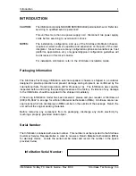
Page 10: ...o provide protection and prevent damage during shipment as confirmed by the International Safe Transit Association ISTA Procedure 1A The InfoStation was carefully inspected before and during the packi...

Page 11: ...lity Additional PBP and SFP modules are available to accommodate a variety of configurations interfaces and applications Refer to Appendix B for further information on optional InfoStation accessories...

Page 12: ...external expansion chassis This guide is intended to supplement documentation provided with the host computer system the operating system and the drive s to be installed within the InfoStation Feature...

Page 13: ...tion Drive Ready Indicates that the drive is properly installed and ready for access Drive Activity Indicates that the drive is being accessed Drive Fault Indicates a drive failure Key Lock s Assure p...

Page 14: ...odule features overvoltage and overcurrent protection total usage hours and power supply fault detection Each module also contains two 2 high pressure variable speed blowers for ample chassis cooling...

Page 15: ...wn Port Bypass Module A Captive Screw Power Supply Module LEDs Power Supply Handle Power Supply Module 1 Blower Vent Power Switch 14FC_03 Module Option Port Bypass Module B Option Power Supply Module...

Page 16: ...guration and control Figure 5 Figure 5 LED Indicator and Control Panel LED Indicator Control Panel Components Power Green ON Power to the chassis is on Warning Amber ON One or more warning conditions...

Page 17: ...One or more drives are being bypassed Reset Resets InfoStation User Interface Module will not reset FC loops RS 232 Serial Port RS 232 serial connection used for InfoStation external monitor ing and...
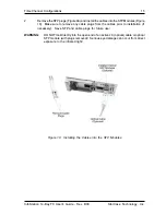
Page 18: ...face Panel Each InfoStation drive carrier provides a User interface for individual carrier operation Drive Ready LED Drive Fault LED Steady glow indicates that drive is inserted and ready for access F...

Page 19: ...ed when removing a disk drive from the drive bay It is the responsibility of the operator to ensure that the host does not access the drive while attempting to remove the disk drive and to follow the...

Page 20: ...and installing the PBP Module Refer to the InfoStation Installation Guide for further information SFP Module is hot swappable The chassis may remain on when removing and installing the SFP Module HSSD...

Page 21: ...e forced into bypass Loop A ON Error detected in the Loop A data input Data In Error Loop A ON Error detected in the Loop A data output Data Out Error Loop B ON Error detected in the Loop B data input...

Page 22: ...tion Auto Loopback is enabled when there are no SFP Modules installed in the open Host ports An additional PBP Module is available as an upgrade Contact StorCase for further ordering information Depen...

Page 23: ...onfigurations StorCase Technology Inc InfoStation 14 Bay FC User s Guide Rev B00 Figure 9A Installing the LC optical SFP Module into the PBP Module Figure 9B Installing the HSSDC2 copper SFP Module in...

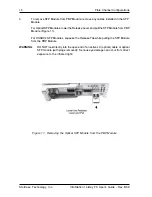
Page 24: ...gure 10 Make sure to remove any cable plugs from the cables prior to installation if necessary Save SFP and cable plugs for future use WARNING DO NOT look directly into the open end of an active LC op...

Page 25: ...he Release Lever and pull the SFP Module from PBP Module Figure 11 For HSSDC2 SFP Modules squeeze the Release Tab while pulling the SFP Module from the PBP Module WARNING DO NOT look directly into the...

Page 26: ...device or chassis settings Please refer to the InfoMon User s Guide for further information Hardware Compatibility To assure maximum system compatibility and performance StorCase recommends Seagate F...

Page 27: ...iscussed in this User s Guide For redundant loop configurations make sure your O S supports disk duplexing mirroring Refer to O S manufacturer s documentation for further information An additional PBP...

Page 28: ...Loop Configuration Multiple Chassis NOTES Auto Loopback is enabled when there are no SFP Modules installed in the open Host ports SFP modules are optional Contact StorCase for further ordering informa...

Page 29: ...ules installed in the open Host ports SFP modules are optional Contact StorCase for further ordering information Up to 9 InfoStations or 126 FC Drives maximum For redundant loop configurations make su...

Page 30: ...ere are no SFP Modules installed in the open Host ports SFP modules are optional Contact StorCase for further ordering information Up to 9 InfoStations or 126 FC Drives maximum FC AL 2 PC FC HBA Host...

Page 31: ...e open Host ports SFP modules are optional Contact StorCase for further ordering information Up to 9 InfoStations or 126 FC Drives maximum For redundant loop configurations make sure your O S supports...

Page 32: ...s installed in the open Host ports SFP modules are optional Contact StorCase for further ordering information Up to 9 InfoStations or 126 FC Drives maximum FC AL 2 FC AL 1 FC AL 3 FC AL 4 PC FC HBA Ho...

Page 33: ...24 Fibre Channel Configurations StorCase Technology Inc InfoStation 14 Bay FC User s Guide Rev B00 This Page Left Blank Intentionally...

Page 34: ...InfoStation 14 Bay FC User s Guide Rev B00 StorCase Technology Inc Appendix A Specifications Dimensions 25 APPENDICES...

Page 35: ...Relative Humidity 1 10 to 80 10 to 90 Altitude 1000 to 10 000 ft 1000 to 40 000 ft 305m to 3048m 305m to 12195m Shock 2 10g 60g 1 Non condensing with maximum gradient of 10 per hour 2 11 msec pulse wi...

Page 36: ...ors Yes Interface SCA Protocol Fibre Channel Transfer Rate 2 Gbps User Interface LED Read Out and Yes Control Panel of Power Supply Blower Modules 1 or 2 Redundant Yes Hot Swappable Yes Speed Variable...

Page 37: ...n Power Cooling Modules StorCase InfoStation Fibre Channel Rack Mount Enclosure External Monitoring Utility Yes via RS 232 Port Power On Hour POH Yes Monitoring Audible Alarm Yes Standard 19 Rack Moun...
Page 38: ...se Technology Inc Appendix A Specifications Dimensions 29 Figure A 1 InfoStation Physical Dimensions Dimensions are for reference only Top View Right Side View Front View 5 21 132 3mm 20 57 522 5mm 16...

Page 39: ...B Optional Accessories Port Bypass Module The InfoStation s scalable backplane design allows additional modules to be offered supporting a variety of FC configurations An additional PBP module P N S1...

Page 40: ...ev B00 StorCase Technology Inc Appendix B Optional Accessories 31 SFP Modules HSSDC2 Copper SFP Module P N S10D108 Figure B 3 LC Optical SFP Modules Figure B 2 HSSDC2 Copper SFP Modules 14FC_14 14FC_1...

Page 41: ...32 Appendix B Optional Accessories StorCase Technology Inc InfoStation 14 Bay FC User s Guide Rev B00 Figure B 4 Patch Cable Kit Patch Cable Kit P N S90D100...

Page 42: ...t method to attach the InfoStation to a rack mount enclosure Figure B 5 These high quality durable rails provide 24 ball bearing rollers and have a quick release button which allows quick and easy ins...

Page 43: ...BLE PARTS inside the unit Warranty is VOID if module is opened Refer ALL servicing to qualified service personnel NOTE Refer to the InfoStation Installation Guide for further information An optional s...

Page 44: ...se Technology Inc Appendix B Optional Accessories 35 Drive Carrier Spare drive carriers P N S10A116 are available for the InfoStation chassis as shown in Figure B 7 Contact StorCase for further orderi...

Page 45: ...designed to transport the InfoStation drive carrier from one site to another in a safe impact and moisture resistant environment Its compact dimensions 7 long x 9 wide x 4 high make it easy to carry...
Page 46: ...ck mount InfoStation to a tower conversion as shown in Figure B 9 Contact StorCase for further ordering information Top Cover Top Cover Base Left Cover Bezel Base Pan Hd Screw 4 Total Pan Hd Screw 1 T...

Page 47: ...to monitor the statuses and temperatures of individual InfoStation modules and drive bays etc and can provide real time updates via an Internet connection With the recent addition of the InfoMon Call...

Page 48: ...the installation instructions Everyone at StorCase Technology is working toward the goal of providing you with the highest quality most cost effective products available on the market and we need you...

Page 49: ...THIS LINE AND STAPLE SHUT CUT ALONG THIS LINE FROM BOTTOM TO TOP OF PAGE BUSINESS REPLY MAIL POSTAGE WILL BE PAID BY ADDRESSEE NO POSTAGE NECESSARY IF MAILED IN THE UNITED STATES FIRST CLASS MAIL PERM...

Reviews: