background image

Stollmann  

E + V GmbH 

C11/G2


User Guide 


Author: ta 

Date saved: 06.04.09 

Ref: C11G2_User_Guide_r02.doc 

Revision: r02 

Page 19 of 22 


5  Firmware Update 

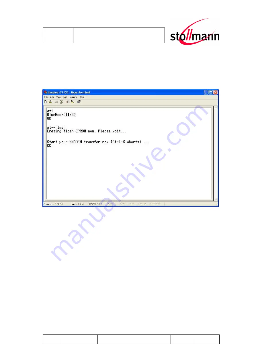
For flashing new firmware, power-on the C11/G2, open a terminal 
emulation program and start the update with the “AT**FLASH” command.


Figure: Firmware update with “AT**FLASH” command 

After a few seconds, the following message will be displayed: 
    “Erasing flash EPROM now. Please wait ...” 

A few seconds later the following message will be displayed: 
    “Start your XMODEM transfer now (Ctrl-X aborts) ...” 

Start the upload transfer. Search for the firmware file to load into the device and 
upload the file using the 1k X-Modem protocol. 
 

Summary of Contents for BlueEva+C11/G2

Page 1: ...Stollmann E V GmbH BlueEva C11 G2 User Guide Author ta Date saved 06 04 09 Ref BlueEva C11G2_User_Guide_r02 doc Revision r02 Page 1 of 22 BlueEva C11 G2 User Guide Version r02 Date Apr 2009 ...

Page 2: ... devices may occur due to individual differences between such devices Device samples were tested in a reference environment for compliance with the legal requirements applicable to the reference environment No representation is made regarding the compliance with legal regulatory or other requirements in other environments No representation can be made and no warranty can be assumed regarding the s...

Page 3: ...ion Between two BlueEva C11 G2 Using the Serial Port Profile SPP 8 3 3 2 Automatically Establishing a Bluetooth Connection Between Two BlueEva C11 G2 Using Auto Connect 9 4 Hardware 13 4 1 Bluetooth Modules 13 4 2 Power Supply 13 4 3 Reset 14 4 4 Antenna 14 4 5 Serial Interface 15 4 6 Connectors Jumpers 15 4 6 1 Jumper J1 15 4 6 2 Jumper J2 16 4 6 3 Jumper J3 16 4 6 4 Connector X1 17 4 7 Default F...

Page 4: ...of 22 1 Introduction This documentation describes the use of the Stollmann BlueEva C11 G2 Bluetooth evaluation board 2 Equipment The following components are included with each BlueEva C11 G2 evaluation kit 2x BlueEva C11 G2 board 2x Power supply 5 VDC 2x Serial cable RS232 2x USB cable 10x additional jumper 1x BlueEva C11 G2 CD ROM ...

Page 5: ...ure BlueEva C11 G2 as delivered The USB connection may be used as an alternative to the 5 VDC mains adapter The USB port is exclusively used to supply the BlueEva C11 G2 with power It does not serve any additional functions You may connect the RS232 connector to the COM port of a PC This lets you use a terminal emulation program such as HyperTerminal to perform the configuration and control the Bl...

Page 6: ...ase consult our AT Command Reference With default settings the BlueEva C11 G2 works at 115 200 bps using the 8N1 data format 8 data bits no parity 1 stop bit Please configure your terminal emulation program accordingly Figure COM port configuration with HyperTerminal Once you have successfully configured the emulation program issuing the AT command without parameters should prompt the BlueEva C11 ...

Page 7: ...02 doc Revision r02 Page 7 of 22 Finally you should use the AT BOAD command to determine the Bluetooth address of the BlueEva C11 G2 and note it The Bluetooth address is unique letting you identify the correct device for each Bluetooth address Figure Reading some BlueEva C11 G2 settings with HyperTerminal ...

Page 8: ...hapter 3 2 Configuration You can either use a single PC with 2 COM ports or two separate PCs with one COM ports each Now you can establish a connection from one BlueEva C11 G2 to another by issuing the ATD Bluetooth Address command Figure Establishing a Bluetooth connection between two BlueEva C11 G2 If the connection was established successfully the originating BlueEva C11 G2 will issue the messa...

Page 9: ...vice without having to take control manually This requires that you store the Bluetooth address of the remote device on the BlueEva C11 G2 The following figures describe the steps needed to run the BlueEva C11 G2 in Auto Connect mode The BlueEva C11 G2 can be configured to different auto connect modes In this example we read out the Bluetooth address of BlueEva C11 G2 A and set it to command set 1...

Page 10: ... B with Auto Connect Now the BlueEva C11 G2 B will attempt to automatically establish a Bluetooth connection to the remote device which in our example is the second BlueEva C11 G2 A If the connection was established successfully the LED 2 indicates the successful Bluetooth connection ON Bluetooth connection is established You can now send data transparently between the two BlueEva C11 G2 ...

Page 11: ...nate the Auto Connect mode you will have to turn off the BlueEva C11 G2 B device configure your terminal emulation to 9 600 bps Figure COM port configuration with HyperTerminal Turn on the BlueEva C11 G2 again and wait for the Press CR CR ESC ESC to enter BlueRS configurator message Figure Enter the configuration mode and load the default settings ...

Page 12: ...you can enter the configuration mode with CR CR ESC ESC within 2 seconds and load the default values of the module using the defa 1 and save command For the BlueEva C11 G2 to retain the Auto Connect setting correctly the unit will have to be cycled off and back on For more information about auto connect please consult our AT Command Reference ...

Page 13: ...lueEva C11 G2 is populated with a BlueMod C11 G2 Bluetooth module 4 2 Power Supply There are two variants of supplying power to BlueEva C11 G2 5VDC 10 from external power supply connector 5VDC 10 from USB VBUS The power source can be selected by jumper J4 Jumper Position Function 1 2 Power from USB J4 2 3 Power from power socket The presence of the power supply voltage is indicated by the power LE...

Page 14: ... 04 09 Ref BlueEva C11G2_User_Guide_r02 doc Revision r02 Page 14 of 22 Figure Power supply by external power supply Figure Power supply by USB 4 3 Reset The BlueEva C11 G2 is equipped with a reset button 4 4 Antenna The BlueEva C11 G2 is equipped with an onboard antenna ...

Page 15: ... a special setting in the firmware The selection of the appropriate D SUB socket is made by jumper J2 20 Jumper Position Function 1 2 DCE socket selected J3 7 2 3 DTE socket selected 4 6 Connectors Jumpers 4 6 1 Jumper J1 Jumper J1 is used for signal routing Jumper Number Position Description J1 1 Open Not used J1 2 2 3 connect PIO9 to LED2 J1 3 Open Not used J1 4 2 3 connect PIO7 to LED1 J1 5 2 3...

Page 16: ...en using the GPIOs or AIOs as outputs pin 2 will be used to access the signal Jumper Number Description J2 0 GPIO0 J2 1 GPIO1 J2 2 GPIO2 J2 3 GPIO3 J2 4 GPIO4 J2 5 GPIO5 J2 6 GPIO6 J2 7 GPIO7 J2 8 GPIO8 J2 9 GPIO9 J2 10 GPIO10 J2 11 GPIO11 J2 12 GPIO12 J2 13 GPIO13 J2 14 GPIO14 J2 15 GPIO15 J2 16 GPIO16 4 6 3 Jumper J3 Jumper block J3 allows the configuration of debug settings USB support and DTE ...

Page 17: ...0 PCM_SYNC I O PCM Frame Sync Slave I Master O 11 PIO15 I O Digital Input Output 12 PIO14 I O Digital Input Output 13 PIO13 I O Digital Input Output 14 PIO12 I O Digital Input Output 15 PIO11 I O Digital Input Output 16 PIO10 I O Digital Input Output 17 PIO9 I O Digital Input Output 18 PIO8 I O Digital Input Output 19 PIO7 I O Digital Input Output 20 PIO6 I O Digital Input Output 21 PIO5 I O Digit...

Page 18: ...IO7 connected to LED1 J1 5 2 3 PIO 6 connected to RI on DTE DCE socket J1 6 2 3 PIO 14 connected to DTR DTE and DSR DCE output on DTE DCE socket J1 7 2 3 PIO 13 connected to DSR DTE and DTR DCE input J1 8 2 3 PIO 15 connected to DCD for DTE and DCE J1 9 1 2 RTS connected to DTE DCE socket J1 10 1 2 TXD connected to DTE DCE socket J1 11 1 2 RXD connected to DTE DCE socket J1 12 1 2 CTS connected to...

Page 19: ...tion program and start the update with the AT FLASH command Figure Firmware update with AT FLASH command After a few seconds the following message will be displayed Erasing flash EPROM now Please wait A few seconds later the following message will be displayed Start your XMODEM transfer now Ctrl X aborts Start the upload transfer Search for the firmware file to load into the device and upload the ...

Page 20: ...rotocol After loading the complete firmware into flash memory the device responds with the message Starting new firmware now and automatically performs a reset Now you shall send the following commands to set firmware default parameter values AT F1 W Make sure the new firmware file is present and enter ATI99 to check the firmware version number Figure Load factory defaults and check firmware versi...

Page 21: ...nd full or half duplex operation by jumpers Jumper Number Position Description J1 2 3 Half duplex mode RTS connected to RE J1 1 2 Full duplex mode RE connected to GND J2 Close for two wire mode half duplex J3 Close for two wire mode half duplex J4 close Transmitter enable J5 Close for bus termination with 120R J6 Close for bus termination with 120R 7 Restrictions Not all firmware versions support ...

Page 22: ...uide_r02 doc Revision r02 Page 22 of 22 8 History Version Date by Changes since last version 1 00 04 07 2007 MBu Initial version r01d01 30 072007 fh New revision system typos grammar r01 17 08 2007 JW reviewed corrected Jumper tables translations r02 06 04 2009 HB Added new chapter 6 RS 485 Interface ...

Reviews: