background image

20IP18B

1

1

INTRODUCTION

1.1

General

Through their unique construction, these water heaters are
renowned for their:

1.2 Supplier 

StokvisEnergySystems

1.3

This manual

This documentation has been to aid the following target

-  high thermal efficiency
- environmental 

friendliness

-  light weight and small dimensions
- durability
-  low noise production
-  large regulating range
-  available with many different options.

Continual research and development means that 

Stokvis

remains at the forefront of boiler and water heater technology.

96R Walton Road
East Molesey
Surrey
KT8 0DL

Tel.: 0

8707 707 747

Fax: 0

8707 707 767

For advice or more information with regard to our products 
contact 

Stokvis

.

groups:
-  the consulting engineer
-  the heating installer
-  the service engineer
- the 

user

Because these target groups require mostly similar information
and also specific information, our technical documentation has
been integrated to provide these target groups with the neces-
sary general and specific information to install, service and
operate this product.
The supplier (see 1.2) will be able to provide any further or
supplemental information.

Summary of Contents for ECONOPAK R2000

Page 1: ...INSTALLATION OPERATION MAINTENANCE DOCUMENTATION STOKVIS ENERGY SYSTEMS 96R WALTON ROAD EAST MOLESEY SURREY KT8 0DL TEL 020 8783 3050 08707 707 747 FAX 020 8783 3051 08707 707 767 E MAIL info stokvisboilers com WEBSITE www stokvisboilers com 20IP18B 220802 ...

Page 2: ...rding or otherwise without the prior permission in writing of Stokvis We aim to achieve continuous improvement in our products Therefore specifications are subject to change without prior notice Due to changes the product can deviate from the information specified in this document Therefore Stokvis rejects any responsibility for the differences between the product delivered and the information men...

Page 3: ...sure relief valve connection 1 1 1 1 1 1 relief connection 1 1 1 1 1 1 standard setting bar 5 5 5 5 5 5 5 5 5 5 5 5 Electrical supply water heater 1N V 230 230 230 230 230 230 230 230 230 230 230 230 pump 3N V 400 400 400 400 400 400 400 400 400 400 400 400 Frequency Hz 50 50 50 50 50 50 50 50 50 50 50 50 Fuse A 6 6 6 6 6 6 6 6 6 6 6 6 Max electrical consumption water heater kW 0 04 0 04 0 04 0 04...

Page 4: ...20IP18B IV Fig 1 Dimensions Dimensions The R2000 unit is also available as a left handed model Top and side clearances are 600 mm MINIMUM ...

Page 5: ...20IP18B V Fig 2 Dimensions 300 litre tank Fig 3 Dimensions 500 litre tank R2000 ECONOPAK PLUS with BT 300 litre tank R2000 ECONOPAK PLUS with BT 500 litre tank ...

Page 6: ...20IP18B VI ...

Page 7: ...sport 15 5 INSTALLATION 17 5 1 Boiler room 17 5 1 1 Siting 17 5 1 2 Boiler room ventilation 17 5 2 Unit connections 18 5 2 1 Gas supply 18 5 2 2 Electrical supply 18 5 2 3 Hydraulic connections 19 5 2 3 1 Water system 20 5 2 3 1 Pump information 20 5 2 4 Flues 22 5 3 General recommendations 23 5 4 Water temperature 24 5 5 Demand for hot water for sanitary use 24 5 6 Water quality 25 5 7 Formula to...

Page 8: ...N AND FAULT INDICATION 40 7 1 Function 41 7 2 Regulation 41 7 3 Control panel 41 7 4 Fault indications 41 7 5 Start up 41 7 6 Shut down 41 7 7 Warnings 41 7 8 Fault finding table 42 8 MAINTENANCE 44 8 1 Safety 44 8 2 General information 44 8 3 Inspection 44 8 4 Cleaning 45 8 5 Servicing 46 8 6 Component replacement 50 8 6 Service 54 9 LIST OF SERVICEABLE PARTS 55 SUPPLEMENT 56 ...

Page 9: ...remains at the forefront of boiler and water heater technology 96R Walton Road East Molesey Surrey KT8 0DL Tel 08707 707 747 Fax 08707 707 767 For advice or more information with regard to our products contact Stokvis groups the consulting engineer the heating installer the service engineer the user Because these target groups require mostly similar information and also specific information our te...

Page 10: ...y of manufactur ers and suppliers of products for use at work to ensure so far as it is reasonable practicable that such products are safe and without risk to health when properly used and to make available to users of such products adequate information about their safe and proper operation Andrews water heaters should only be used in the manner and purpose for wich they were intended and in accor...

Page 11: ...ent in the burner assembly The load at nett calorific value is approx 3 5 kW per burner All water heater types are fitted with a 9 tube heat exchanger of the 2 pass type The use of extruded copper fin pipes in the heat exchanger leads to higher efficiency Thermal radiation losses are minimized by the optimal con struction of the combustion chamber in which high grade insu lation is integrated The ...

Page 12: ...sides 4 Connection box 15 Main gas valve 5 Servomotor air damper gas input 16 Gas train cover 6 Pressure test point 17 Filling and drain valve 7 Gas modulating valve 18 Pressure relief valve 8 Air damper 19 Water flow switch 9 Main burner gas governor 20 Instrumentation panel 10 Gas connection 21 Inspection panel electrical wiring 11 Electrodes controls 12 Sight glass 22 Cable glands ...

Page 13: ...ntle is easily removed without the use of any special tools by means of a click system Combustion chamber The chassis consists of two side frames with steel supports Dura blanket type thermal insulation is sandwiched between the vermiculite refractory blocks and front rear and side panels of the combustion chamber housing These vermiculite refractory blocks are mounted so as to allow freedom of ex...

Page 14: ...rally into a mounting plate The baffles on the copper fin tubes optimize the efficiency of the heat exchanger The stain less steel supply and return pipes together with the water mani folds form the heat exchanger Primary pump The primary circulating pump is sized to prevent the depositing of limescale in the water heater under the following conditions Water hardness in ppm Maximum temperature in ...

Page 15: ...njector nozzle mounted on the gas manifold Combustion air damper A combustion air damper is situated underneath the burners Gas train The principal components of the gas train are a main governor and two main gas valves or combined main governor and main gas valve The quantity of gas is adjusted in proportion of the quantity of air being supplied by the air damper opening The pilot flame has a sep...

Page 16: ...t temperature C Burner enable not applicable D Mod indicator decrease fire rate E Mod indicator increase fire rate F Two stage firing not applicable G Limit comparator H Manual operation The keys K L M N are used for displaying values and changing parameters in the temperature controllers configuration K Down key reduce value L Up key increase value M Programme key N Exit key Assignment of levels ...

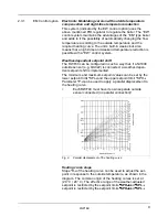
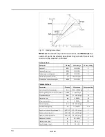
Page 17: ... system Weather dependent setpoint shift The RWF40 can be configured in such a way that if a Ni1000 outside sensor e g QAC22 is connected a weather depen dent setpoint shift is implemented The minimum and maximum setpoint values can be set by the lower setpoint limit SPL and the upper setpoint limit SPH Parameter P can be used to apply a parallel displacement to the heating curve Each RWF40 must h...

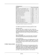
Page 18: ... SPH 1 Parameter level Parameter Display Value range Factory setting Limit value of limit comparator AL 1999 9999 digit 0 1 Switching differential for limit comparator HYSt 0 999 9 digit 1 1 Proportional band Pb 1 0 1 999 9 digit 10 1 Derivative time dt 0 9999 s 80 Integral action time rt 0 9999 s 350 Contact spacing db 0 0 999 9 digit 1 1 Actuator running time tt 10 3000 s 15 s Switch on threshol...

Page 19: ... water flow switch The water flow switch is installed in the flow manifold and monitors continuously the minimum water flow If the water flow falls below a preset level the burner is shut down and go to lock out The water flow switch is factory set and should not be adjusted high limit thermostat In the event of failure of the control thermostat a preset high limit thermostat will shut down the bu...

Page 20: ...ccording to the current national and local demands norms and standards The installation procedure should only be used for heating systems with a maximum water temperature of 95 C We emphasize that you should always give priority to the above mentioned standards and regulations and that the installation regulations should be considered as an addition to these stan dards and regulations Explanation ...

Page 21: ...om the electric mains and close the gas service cock in the gas supply pipe before com mencing maintenance and servicing operations Check the system for leaks afterwards follow the standard safety regulations to prevent accidents Cover panels should only be removed for maintenance and servicing tasks Replace all panels after completing these maintenance and servicing tasks The installation should ...

Page 22: ... sure that you follow all safety instructions properly Operation In case of gas leakage switch off the water heater and close the gas service cock Open doors and windows and notify the proper authorities Follow the instructions in the manual when you use the water heater again Technical specifications Do not exceed the specifications as layed down in the installa tion and maintenance instructions ...

Page 23: ...apper Check for damage after removing the water heater s protective covering Check whether the water heater conforms to the order require ments Check whether the circuit diagram and gas train diagram num ber is in accordance with the offer order confirmation and the data on the water heater s data number plate covering The panel work is also covered in a protective poly ethylene layer Before final...

Page 24: ...t truck When moving the water heater with a pallet cart or forklift truck the forks should be placed at a front of the water heater Using a crane Always use special lifting harnesses which should be placed on the water heater Make sure that during lifting the harness does not damage the draught diverter ...

Page 25: ...orting it s weight and any necessary equipment If the water heater is to be installed on a raised plynth the plynth must carry forward by at least 1100 mm in front of the water heater to allow removal of the burner trolley It is important that the boiler is sited so that extraneous material cannot be stored next to it and standards Air supply and ventilation It is important that there is an adequa...

Page 26: ...an be found at the right side of the water heater The main gas service cock and gas filter should be supplied by a qualified heating engineer Install the main gas service cock and the gas filter as close to the water heater as possible The R2000 series of water heaters are suitable for connection to a 25 mbar gas network The minimum supply pressure must never fall below 18 mbar With a lower gas pr...

Page 27: ...uired for the primary pump Pump switching The primary pump supplied with the water heater should be wired to ensure constant operation whilst the water heater is in use and to give an over run facility when the water heater is switched off An automatic over run system is available as an optional extra according to the current national and local demands norms and standards The cold water feed recir...

Page 28: ...ter heater but can be supplied on the left hand side by special order i e standard or alternative handing The water heater is suitable for a maximum operating pressure of 6 6 bar It is important that a suitable sized secondary circulation pump is fitted in the return to the water heater Water treatment and suitable filtration is recommended for these water heaters and advice should be obtained fro...

Page 29: ...ressure drop H in in m h meter water gauche 3 R2017 14 5 2 1 R2022 14 0 2 2 R2028 13 5 2 4 R2034 19 5 3 0 R2041 19 0 3 1 R2048 18 5 3 2 R2056 18 0 3 35 R2066 17 5 3 45 R2077 17 0 3 55 R2090 24 5 6 6 R2105 24 0 6 8 R2122 23 5 7 1 Table 4 Water flow rate and pressure drop ...

Page 30: ...3 20 A TP 50 120 PN10 Table 5 Pump motor rating A 400 V electrical supply is normally required for the primary pump Flue dimensions You can use the following flue dimensions to assist in flueing Type Q flue m h Chimney 3 diameter mm R2017 230 200 R2022 298 225 R2028 376 250 R2034 454 250 R2041 551 300 R2048 645 300 R2056 749 350 R2066 885 350 R2077 1013 400 R2090 1206 400 R2105 1407 450 R2122 1516...

Page 31: ...ct exit velocity less than 8 m sec See for further instructions Supple ment The cold water feed pipes should be installed and protected in accordance with local regulations Generally this means that a check valve and an expansion valve should be fitted Hot water pipes should be thermally insulated In order to maintain a constant temperature at all outlets it is necessary to have a return circuit w...

Page 32: ...f 36 C To achieve this a slow operating motorised valve controlled by a thermostat in the secondary return is required temperature of 43 C are temperature losses in the pipework a temperature of 60 C is considered suitable Installations supplying large kitchens demand much higher temperatures For degreasing a temperature of 65 C is re quired for sterilising 85 C In this case the hot water supply u...

Page 33: ...shing 10 people 150 300 35 5 10 per outlet 6 people 120 180 35 6 12 per outlet shower 60 80 40 10 15 Taps fitting capacity diame ter in mm 10 half open 40 5 15 half open 40 10 20 half open 40 25 fully open 40 10 fully open 40 18 fully open 40 45 Table 8 Delivery from fittings Water hardness The hardness of water is caused by the dissolved salts of calcium and magnesium principally carbonates sulfa...

Page 34: ...hether the water is acid or alkaline A solution is acid when pH is less than 7 A solution is alkaline when the pH is greater than 7 The pH is measured at 25 C A pH of 7 corresponds to a neutral water The pH varies with temperature See graph A below The pH of the water is very important as it influences precipitation of the carbonates The pH of water is generally between 6 5 and 7 5 The temporary h...

Page 35: ...aximum pH Maximum operating ppm temperature in C 0 80 8 4 90 80 250 7 6 85 250 350 7 2 80 350 500 7 0 60 Table 10 Maximum operating level When the operating temperature exceeds the high limit set tings the water heater will be turned off and will not go to lock out From table 11 select the application the number of hot water units and the formula to apply From table 12 as a function of the number ...

Page 36: ... wash 0 5 4 restaurant 15 100 4 hairdresser 3 seat 1 beauty salon 4 assistant 1 offices 1 washroom 1 meals sitting Institutions sport club 5 shower 4 school 4 shower 3 factory 5 shower 2 4 hospital 2 or 3 bed 1 2 0 5 tap 0 5 tap 1 tap Table 11 Application numbers Formula for application Hot water units 1 Low demand Q G x 28 output in W 60 2 Medium demand Q G x 35 output in W 60 3 High demand Q G x...

Page 37: ...nstant draw or small fluctu 5 8 2 Dual temperature With storage tank 300 l or 500 l system Applicable to projects where exact temperatures have to be ations without large peak load Such as hotels without catering towards the tour operators hospitals chemical industry food processing dairy produce etc adhered to or in projects with large peak loads and fast chang ing water demands High rise apartme...

Page 38: ...to be kept within small tolerances Industrial applications such as carwash removing of protective wax layer photo and film processing laboratories plating processing slaughterhouses etc This application finds its way in projects with large peak loads in regular intervals Schools washing fountains at manufacturing facilities Laundromats etc Other applications Bottle cleaning and desinfection crate ...

Page 39: ... heat exchanger is free of any such deposits after flushing the system Water heating system fill the system up to the standard set pressure bleed the system switch on all pumps and check for correct direction of rota tion close the stop valves in the secondary system check the water heater electrical connection switch on the water heater with the ON OFF switch adjust the temperature regulator to t...

Page 40: ... 1 3 2 1 5 R2048 0 9 3 5 4 1 3 2 1 5 R2056 0 8 3 0 4 1 3 2 1 5 R2066 0 8 3 0 4 1 3 2 1 5 R2077 0 8 3 0 4 1 3 2 1 5 R2090 0 8 3 0 4 1 3 2 1 5 R2105 0 8 3 0 4 1 3 2 1 5 R2122 0 8 3 0 4 1 3 2 1 5 full load 100 Type Burner Pilot Air Burner Cascade pressure pressure damper pressure in mbar mbar mm mbar mbar opening 40 ET EM only closed out in R2017 10 4 3 5 90 1 3 2 7 5 R2022 10 4 3 5 90 1 3 2 7 5 R202...

Page 41: ... 8 13 18 6 R2066 5 2 11 8 13 18 6 R2077 5 2 11 8 13 18 6 R2090 5 2 11 8 13 18 6 R2105 5 2 11 8 13 18 6 R2122 5 2 11 8 13 18 6 full load 100 Type Burner Pilot Air Burner Cascade pressure pressure damper pressure in mbar mbar mm mbar mbar opening 40 ET EM only open out in R2017 40 11 90 13 18 28 R2022 40 11 90 13 18 28 R2028 40 11 90 13 18 28 R2034 40 11 90 13 18 28 R2041 40 11 90 13 18 28 R2048 40 ...

Page 42: ...en purged in accordance with IM 2 or BS 6891 as appropriate IV Check that all electrical supplies are isolated V Check electrical earth continuity between the water heater gas pipework and the mains supply VI Check the electrical components are of the correct vol tage range particularly low voltage ancillary controls VII Check the pump motor current and adjust the starter overload settings VIII Fi...

Page 43: ...closes that there is a spark at the ignition elec trode that the pilot safety shut off valve is heard to be opening and that the water heater goes to lockout in approximately 5 secs later as there is no gas gas train downstream of the gas inlet service cock as follows Refer to Gas trains fig 30 for particular water heater model 1 Ensure that gas service cock and pilot manual cock are closed 2 Conn...

Page 44: ...and open pilot manual cock 13 Open and close the gas service cock to pressurise up to the pilot safety shut off valve 14 Allow 1 minute for temperature stabilisation and then check for any loss of pressure at the gauge during the next 2 minutes 15 If there is a pressure loss the pipework upstream of the pilot safety shut off valve should be checked with a suitable leak detection fluid with the gas...

Page 45: ... air damper opens and the gas rate increases to maximum Check the main burner pres sure on maximum is as indicated in table 14a or 14b and adjust if necessary Check all pipework and connections downstream of the safety shut off valves for gas leaks with a suitable leak detection fluid Switch off the water heater remove pressure gauge and close the test point e Remove the RH upper side panel and wi...

Page 46: ...mum against that indicated in table 14a or 14b adjust if necessary at the main burner governor Check this against a gas rate reading at the installation gas meter i Check the operation of the water flow switch by gradu ally closing down one of the water heater isolating valves The water heater should go to lock out j Check that the pump overrun is operating correctly when the water heater is switc...

Page 47: ...heater at the gas service cock and to call the local gas supplier Water heater failure In case of water heater failure the system will fall into lock out Reset the water heater with the reset button on the control panel Repeat this several times if necessary If the water heater still does not start refer to chapter Operation and fault finding 7 ...

Page 48: ... detected by a sens ing electrode The modulating control will commence from low fire condition modulates between 20 and 100 heat demand If the heat demand is smaller than 20 the burner will remain off The temperature is controlled through or an electronic PID regulator EM version number of warning indicators and switches 1 Power on off switched indicator 2 Water heater lock out indicator central a...

Page 49: ...ight click is heard Lamp 4 turns off Refit cap nut Refit upper right hand panel and fasten the two top screws will be off Reset by pushing reset button 3 The pilot flame on the main burner can be observed through the sight glass on the lower right hand side of the water heater see pos 12 fig 4 Start sequence A Turn manual gas cock open B Turn the pumps on C Ensure that all hot water outlets are cl...

Page 50: ...igh enough button through hole in upper RH side panel Air modulating damper HT lead disconnected or correct cycles no ignition spark faulty and water heater then goes to lockout indicator Ignition electrode incor check setting or replace 2 alights rectly set or faulty Faulty ignition generator change Faulty control box change box Ignition sparks pilot Gas supply turned off turn on burner does not ...

Page 51: ...ight Faulty connections to rectify main safety shut off val ve s Faulty main safety shut change valves off valves Faulty control box replace Check ionisation current as per instructions Water heater operates Fault in water system rectify but then goes to over heat indicator 4 alights Main burner pressure set reset too high Pump overrun inopera rectify tive Water heater does not min fire is set too...

Page 52: ...r from the heat exchanger Remove the inner and outer access panels on the draught diverter to allow internal inspection of the draught diverter and flue baffles Heat exchanger external inspection As you inspect the inside of the draught diverter the top of the heat exchanger can also be inspected Check for dirt and sooting For cleaning the heat exchanger refer to section 8 4 Cleaning After removin...

Page 53: ...cleaning Remove the baffles before cleaning the heat exchanger Use compressed air when the heat exchanger is lightly soiled Use a stiff brush and soap when the heat exchanger is very dirty do not allow the refractory brick work to get wet NB example when the instructions are not followed properly This may be caused by insufficient ventilation condensate on the heat exchanger If this is the case cl...

Page 54: ...as train for soundness IV Inspecting the adjustment of the air damper and opera tion of the modulating gas valve and servo motor V Checking the effectiveness of natural or mechanical ventilation VI Inspecting the flue system including terminal for dam age and ensure it is evacuating the products of com bustion without any leakage or spillage VII Check gas pressure settings safety lock out systems ...

Page 55: ... removed Water heater with burner trolley removed 1 Flue outlet socket 2 Down draught diverter 3 Front and rear upper panels 4 Draught diverter air supply opening 5 Water heater heat exchanger 6 Combustion chamber 7 Combustion chamber insulation ...

Page 56: ...emoved each individual burner bar can be removed and cleaned With the exception of the right hand burner bar this is done by first removing the insulation covered stainless steel channels located at the front and rear of the burner assembly and then removing the burner bar by first lifting the end of the burner out of its locating notch and then withdrawing the burner from its injector avoid damag...

Page 57: ...acked Replace the burners starting with the pilot burner Ensure that the shaped venturi end at each burner locates properly over the injector and that the tab at the end of the burner bar locates fully in its notch The two right hand burners have handed tabs to ensure that they are fitted in the correct position as they have cross lighting parts Ensure that the insulation covered stainless steel c...

Page 58: ...ensure the spark electrode is disconnected from the ignition generator Remove the burner assembly frame complete from its location in the burner trolley The ignition and sensing electrodes can now be replaced by removing two security screws and nuts which attach each elec trode to the burner assembly frame When re assembling ensure that the electrodes are correctly replaced with the burner bars in...

Page 59: ... fixing on the valve head Ensure that the new valve head is wired in accordance with the separate supplied wiring diagrams The main gas train is removed as follows Loosen the grub screw securing the keyed shaft of the modula ting valve servomotor to its coupling and remove the motor by unscrewing two fixing screws It is not necessary to remove the gas train if only replacing this component Remove ...

Page 60: ...he locations of the various controls Replace components by removing electrical connections and screw fixings It is necessary to drain the water heater when replacing the water flow switch as it incorporates water connec tions The temperature sensing phials for both the control thermostat and the overheat control are contained within a thermostat pocket in the flow header immediately beneath the co...

Page 61: ...al tool and slide the finned tube mounting plate back into position and remove the special tools Refit and secure the two heat exchanger baffles Inspection of the headers and the fin tube mounting plate mating surfaces Inspect the mating surfaces of the water manifold flow return header and the finned tube mounting plate These should be clean smooth and undamaged O ring replacement Fit new O rings...

Page 62: ... Fin tube replacing 8 6 Service For service and maintenance the service department of your supplier can be contacted Stokvis Energy Systems 96R Walton Road East Molesey Surrey KT8 0DL tel 08707 707 747 fax 08707 707 767 ...

Page 63: ...del 2090 2122 L S VGG20 SKP20 RKM010 RMK010 Modulating gas valve Model 2017 2028 Rmx D 18 2017G1A1 Model 2034 2043 Rmx D 22 2034G1A1 Model 2056 2077 Rmx D 28 2056G1A1 Model 2090 2122 Rmx D 385 2090G1A1 Modulating valve servomotor Berger Lahr STM120Q2 47 8 RMS015 Pilot gas valve Johnson control SM474 RKS025 Ignition transformer L S TQG11A27 ETH010 Flame safeguard relay L S LFL 1 148 RBA004 Control ...

Page 64: ...British Gas publications may be helpful IM 2 Purging procedures of non domestic gas installations IM 5 Soundness testing procedures for industrial and com mercial gas installations IM 11 Flues for commercial and industrial gas installations IM 16 Guidance notes on the installation of gas pipework boosters and compressors Any other requirements currently in force These water heaters are tested to B...

Page 65: ...20IP18B 57 ...

Reviews: