background image

11

4.1  OVER-RUN ADJUSTMENT

The product when served is a combination of air and mix.
Over-run is a measure of the amount of air blended into the
mix.

Over-run can be expressed in terms of the amount of
weight loss for a given volume.  For example, if a pint of
liquid mix weighs 18 ounces and a pint of frozen product
with air added weighs 12 ounces, the over-run is said to be
50 percent (18 oz. - 12 oz. = 6 oz., (6 /12) x 100 = 50%.

The over-run can be checked by placing a one pint
container on an ice cream scale and zeroing out the scale.
Then fill a one pint container with frozen product.  The
container should be filled over the top and leveled with a
straightedge.  The product should not contain any air
pockets.  When weighed on an ice cream scale, one pint
of product should weigh 12 to 13 ounces.

The mix pump has been preset at the factory to produce a
product with approximately 40% overrun.  Because of
differences in mix formulation, temperatures and baromet-
ric pressure, this figure may vary.  It will be necessary for
approximately 2 gallons of mix to be pumped thru the
freezer before changes in the product are noticeable due
to adjustments in overrun.

Overrun is controlled by the length of the air compressor
piston stroke within the piston cylinder.  Lengthening the
stroke within the cylinder will increase overrun.  Con-
versely, shortening the stroke will decrease overrun.  To
perform an overrun adjustment, refer to the following
procedure:

A. Turn the mix pump switch to the OFF position and

unplug the mix pump from its grounded 115V recep-
tacle.

B. Remove the 2 electrical box cover screws and remove

the electrical box cover.

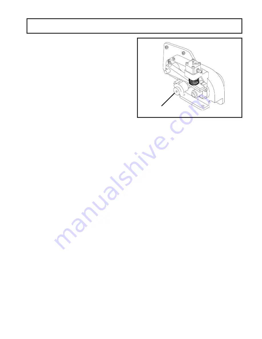
C. On air compressor side of pump, locate the long/

slender piston rocking arm. The rocking arm down-
ward travel is limited by a stationery cam. On the
face of the cam there is an overrun setting indicator
plate numbered 3 thru 8 and an adjustment knob
(Fig. 7).

D. The overrun setting is indicated by a pointed pin.

E. To adjust overrun, loosen the allenhead screw

(located within the center of the adjustment knob)
with the 5/32" allen wrench provided. Rotate the
adjustment knob counterclockwise to a higher
number for higher overrun, or clockwise to a lower
number for lower overrun. Each number multiplied by
10 represents the overrun percentage (ie: #4 = 40%
overrun).

SECTION 4

MAINTENANCE  INSTRUCTIONS

Figure 7

Overrun Adjustment

F. Tighten the allen screw, then place the wrench back

in its clip.  Replace the electrical box cover and
screws, plug the mix pump into its grounded 115V
receptacle and turn the mix pump power switch to the
ON position.

4.2  PREVENTATIVE MAINTENANCE

To assure trouble free operation and consistent over-run
when using the U3 mix pump, we must follow mix hose
repositioning and replacement procedures. The following
is the preventative maintenance schedule:

A. MIX PUMP HOSE REPOSITION (every one or two

weeks.)

NOTE

Mix pump hose must be repositioned every 1 - 2
weeks. Failure to comply will result in reduced mix
pump liquid capacity, dispense stoppage, popping,
and possible mix pump hose leakage.

1. Run cleaning solution through pump.

2. Turn pump off and if connected to freezer, relieve any

pressure by opening the spigot.

3. Grasp the pick-up hose end of the mix pump hose

with one hand and turn the pump on. Pull down on the
pick-up hose end until 12 to 14 inches of tubing has
reversed fed through the pump, then turn the pump
off.

4. Loosen small clamp at the pick-up hose adapter and

disconnect mix pump hose.

5. Cut 7-1/2 inches off the end of the mix pump hose.

The height of the pump can be used to measure. See
Figure 8.

OVERRUN
ADJUSTMENT

Summary of Contents for U3-02

Page 1: ...Model U3 02 OPERATORS MANUAL Manual No 513557...

Page 2: ......

Page 3: ...built prior to date of change DO NOT ATTEMPT to operate the machine until instructions and safety precautions in this manual are read completely and are thoroughly understood If problems develop or q...

Page 4: ...ecific safety information the following safety defini tions are provided to assist the reader The purpose of safety symbols is to attract your at tention to possible dangers The safety symbols and the...

Page 5: ...TION INSTRUCTIONS 7 3 1 Safety Precautions 7 3 2 Pump Motor Switch 7 3 3 Operation Of U3 Mix Pump 7 3 4 Cleaning 8 3 5 Disassembly and Inspection of Removable Parts 8 3 6 Sanitizing and Startup 9 3 7...

Page 6: ...kup Hose 4 C Pickup Hose 4 3 Mix Pump Installation 5 D 4 wayTee Connection 5 4 Pump Motor Switch 7 5 Mix Pump Operation 8 6 Removing Parts 8 7 Overrun Adjustment 11 8 Reposition Mix Pump Hose 12 9 Pum...

Page 7: ...the freezing cylinder of your freezer quickly conveniently Second the U3 Pump precisely injects a preset amount of air into the mix maintaining overruntoassuremaximumprofitability Third itpressur izes...

Page 8: ...2...

Page 9: ...mplete drainage Fig 2 B The product at the mix pump and in transfer lines must be maintained below 41 F 5 C 2 3 INSTALLATION A Follow the steps below to install the mix pump in an upright position on...

Page 10: ...ins to feed See Figure A Figure A 4 Allow the hose to feed itself thru the pump until 6 remains on the entering side 5 Turn pump off 6 Connect mix pump hose to pickup hose adapter using small hose cla...

Page 11: ...ROUND ADAPTER PLUG 2 4 MIX PUMP CHECK OUT Before using the U3 Mix Pump should be thoroughly cleaned This is necessary to remove any foreign materials that may be present A The over run adjustment is p...

Page 12: ...6...

Page 13: ...OTOR SWITCH The PUMP MOTOR switch Fig 4 is located on the mix pump assembly When the pump motor switch is placed in the ON position the mix pump motor will be actuated to pumpmixintothefreezercylinder...

Page 14: ...he clean position and agitate 5 10 minutes maximum 2 Remove suction tube from mix container Draw off the mix remaining in freezer barrel 3 Pump 2 gallons 7 5 liters of cold potable water thru freezer...

Page 15: ...deddisinfectingproductsandproce dures The frequency of cleaning must comply with local health regulations Use a solution containing 100 PPM of free available chlorine Use Stera Sheen Green Label Sanit...

Page 16: ...s on the container and pump through the mix line B Cut a piece of sponge slightly larger than the inside diameter of the mix line Place the sponge inside the mix line and force through with tap water...

Page 17: ...The rocking arm down ward travel is limited by a stationery cam On the face of the cam there is an overrun setting indicator plate numbered 3 thru 8 and an adjustment knob Fig 7 D The overrun setting...

Page 18: ...maining hose is removed from the pump Pressures for Stoelting Freezers Cut out 24 3 PSIG For Duke Freezers Cut out 30 3 PSIG 19 ROLLER DISCHARGESIDE COVER CLAMP PICKUP SIDE CUTLINE MEASUREMENT MIX PIL...

Page 19: ...SSURE IN THIS CASE TURN THEPUMP OFF DRAW 2 3 PINTSTO REDUCE SYSTEM PRESSURETO ZERO TURN PUMP ON PURGEREMAINING AIR IN MIX BAG AND PICK UPHOSE IMPORTANT Before connecting the pick up hose to the mix ba...

Page 20: ...t water Thoroughly clean all mix from pump See Sec 4 2 for hose replacement Lubricate squeeze roller bearings see Item 10 below 9 PUMP HAS POOR CAPACITY Lift and run limits are exceeded Pump is limite...

Page 21: ...owinginformation A Model number of equipment B Serial number of Model Stamped on nameplate C Part number part name and quantity needed Many part names and numbers are listed in this manual NOTE Minimu...

Page 22: ...ch Allen 5 32 11 1995611 1 Wiring Diagram U3 Pump 12 717917 SV 1 Switch Pressure Stoelting 12 717919 SV 1 Switch Pressure Duke 13 3170824 1 Mounting Bracket 14 3171850 1 Splash Guard 15 4177692 1 Pump...

Page 23: ...17 OPTIONAL MOUNTING KIT SEESERVICEREFERENCE PAGE19...

Page 24: ...18...

Page 25: ...19...

Page 26: ...20...

Page 27: ...21...

Page 28: ...22...

Page 29: ...23...

Page 30: ......

Page 31: ...es are subject to the conditions that Buyer a signs and returns to Stoelting upon installation the Checklist Warranty Registration Card for the affected equipment b gives Stoelting prompt written noti...

Reviews: