background image

13

SECTION 5

REPLACEMENT PARTS INFORMATION

5.1 ORDERING PARTS

To assure receipt of the proper replacement parts, supply
your dealer or distributor with the following information:

A.

MODEL NUMBER

 of equipment.

B.

SERIAL NUMBER

 of model (stamped on nameplate).

C.

PART NUMBER, PART NAME, AND QUANTITY
NEEDED.

 Many part names and numbers are listed

on drawings included in this manual.

NOTE

Minimum billing is $50.00.

D.

WIRING DIAGRAMS

 reflect changes in effect with the

Serial Number which are also indicated by a suffix.

5.2 REFERENCE DRAWINGS

The following pages contain reference drawings and parts
lists that will aid the user when operating the freezer.

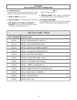
S

G

A

T

D

N

A

S

L

A

C

E

D

R

E

B

M

U

N

T

R

A

P

N

O

I

T

P

I

R

C

S

E

D

5

0

1

4

2

3

K

C

O

H

S

.

T

C

E

L

E

:

N

O

I

T

U

A

C

L

A

C

E

D

7

0

1

4

2

3

S

T

R

A

P

G

N

I

V

O

M

N

O

I

T

U

A

C

-

L

A

C

E

D

1

4

1

4

2

3

S

E

D

A

L

B

G

N

I

T

A

T

O

R

:

N

O

I

T

U

A

C

L

A

C

E

D

8

9

7

4

2

3

H

C

T

I

W

S

E

V

R

E

S

-

F

F

O

-

N

A

E

L

C

-

L

A

C

E

D

8

0

2

4

2

3

K

C

E

H

C

K

A

E

L

.

G

I

R

F

E

R

-

L

A

C

E

D

3

9

3

4

2

3

O

G

O

L

L

R

I

W

S

G

N

I

T

L

E

O

T

S

-

L

A

C

E

D

9

0

5

4

2

3

)

E

K

A

H

S

&

S

S

(

G

N

I

N

A

E

L

C

-

L

A

C

E

D

6

6

5

4

2

3

.

.

.

O

T

G

N

I

D

R

O

C

C

A

D

E

R

I

W

-

L

A

C

E

D

6

8

6

4

2

3

Y

L

L

A

C

I

T

A

M

O

T

U

A

S

T

R

A

T

S

R

E

G

N

A

D

-

L

A

C

E

D

9

8

6

4

2

3

Y

L

B

M

E

S

S

A

L

A

E

S

R

A

E

R

-

L

A

C

E

D

9

9

7

4

2

3

F

F

O

/

N

O

P

M

U

P

-

L

A

C

E

D

1

0

8

4

2

3

W

O

L

X

I

M

-

L

A

C

E

D

Summary of Contents for Optima SO218

Page 1: ...Optima SO218 318 OWNER S MANUAL Manual No 513571 Aug 2001 Rev 2 ...

Page 2: ......

Page 3: ...d are certified in the Stoelting Technicare program Model No _______________________ Serial No _______________________ Purchase Date ____________________ Start Up Date ____________________ CALL Distributor _________________________ Phone No _________________________ fill in or affix label ...

Page 4: ......

Page 5: ...zer without notice and without incurring any obligation to modify or provide new parts for freezers built prior to date of change DO NOT ATTEMPT to operate the freezer until instructions and safety precautions in this manual are read completely and are thoroughly understood If problems develop or questions arise in connection with installation operation or servicing of the freezer contact the comp...

Page 6: ......

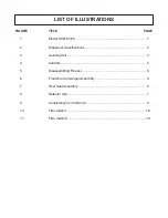
Page 7: ...ning the Freezer Parts 6 3 5 Sanitize Freezer and Freezer Parts 6 3 6 Assembly of Freezer 6 3 7 Sanitizing 7 3 8 Cleaning Sanitizing of SO318 with Fill o matic II and Fill o matic III 8 3 9 Initial Freeze Down and Operation 8 3 10 RemovingProduct 8 3 11 SO218 318 Operation 9 4 PREVENTATIVE MAINTENANCE 4 1 RoutineCleaning 11 4 2 PreventativeMaintenance 11 4 3 Extended Storage 11 4 4 ConsistencyAdju...

Page 8: ...enser Specifications 2 3 LevelingUnit 3 4 Controls 5 5 Disassembling Freezer 6 6 Front Door and Auger Assembly 6 7 Rear Seal Assembly 6 8 Retainer Clip 7 9 ConsistencyControlKnob 8 10 Fill o maticII 16 11 Fill o maticIII 18 LIST OF ILLUSTRATIONS ...

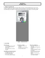
Page 9: ...acity 15 18 gallons per hour output Thick stackable slush for post mixing Or ready to serve pre mixed products High Efficiency Evaporator Auger Stainless steel construction Long life auger blades Quiet smooth operation 8 qt freezing cylinder capacity Consistency Control Adjustable for thick or thin products Sensitive to product demand 24 volt control circuits Dispensing Head Door No Freeze design ...

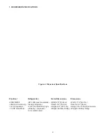
Page 10: ... 7cm 20amp circuit plug friendly refrigerant Depth 30 76 2cm Depth 26 1 66cm 12 running amps 2 HP 14 800 BTUH high Height 66 167 7cm Height 61 2 155cm w casters 1 2 HP Drive Motor efficiency compressor Weight 400lbs 182kg Weight 350lbs 159kg Air or water cooled 1 3 DISPENSER SPECIFICATIONS Figure 2 Dispenser Specifications ...

Page 11: ...crate the freezer B The freezer must be placed in a solid level position To level adjust casters C The freezer is equipped with an air cooled condenser and requires correct ventilation the front is the intake and the back is the discharge Both front and back require 3 clearance for proper operation D Place all switches in the OFF position 2 2SHIPMENTANDTRANSIT The freezer has been assembled operat...

Page 12: ...WIRING If permanent wiring is required by local codes the follow ing procedure must be performed WARNING DISCONNECT FREEZER FROM THE SOURCE OF ELECTRICAL SUPPLY BEFORE SERVICING A Remove the right side panel and electrical box cover to gain access to the power cord connection B Disconnect the black and white wires from the termi nal block L1 and L2 Disconnect the green ground wire from the groundi...

Page 13: ...T BE PLACED IN THE OFF POSITION WHEN DISASSEMBLING FOR CLEANING OR SERVICING THE FREEZER MUST BE DISCONNECTED FROM ELECTRICAL SUPPLY BE FORE REMOVING ANYACCESS PANEL B CLEAN OFF SERVE Switch The CLEAN OFF SERVE switch is a three position toggle and refrigeration switch used to control the operation of the agitator When the switch is placed in the CLEAN position the agitator will rotate When the sw...

Page 14: ...er and clean with brushes provided Rinse all parts with clean hot water CAUTION DO NOT DAMAGE PARTS BY DROPPING OR ROUGH HANDLING B Wash the freezer barrel with warm detergent water and brushes provided C The exterior should be kept clean at all times to perserve the lustre of the stainless steel A mild alkaline cleaner is recommended Use a soft cloth or sponge to apply the cleaner D Remove the dr...

Page 15: ...HE UNITED STATES DEPARTMENT OF AGRI CULTUREAND FOOD AND DRUGADMINISTRA TION REQUIRE THATALL CLEANINGAND SANI TIZING SOLUTIONS USED WITH FOOD PRO CESSING EQUIPMENT BE CERTIFIED FOR THIS USE USE STERA SHEEN OR EQUIVALENT When sanitizing the freezer refer to local sanitary regulations for applicable codes and recommended sanitizing products and procedures The frequency of sanitizing must comply with ...

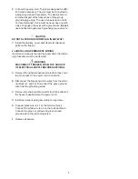
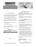
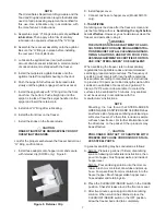
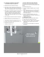
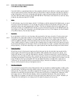
Page 16: ... 5 H Assemble per Section 3 3 6 I Sanitize per Section 3 3 7 Figure 9 Consistency Control Remove plug to access consistency adjustment screw Ê Ê Ê Ê Ê 3 9 INITIAL FREEZE DOWN AND OPERATION This section covers the recommended operating procedures to be followed for the safe operation of the freezer A Sanitize just prior to use B Place the CLEAN OFF SERVE switch in the OFF position C With the spigot...

Page 17: ...ht mode or standby mode If product is left in the freezer overnight we recommend to simply turn the freezer off Do not run the freezer in clean overnight Freeze down time will typically be 6 10 minutes depending on the type of product used and the starting product temperature 3 Pump Operation When the mix level in the hopper drops below the bottom level probe the solenoid valve opens and the pump ...

Page 18: ...10 ...

Page 19: ... 2 If the condenser is dirty using compressed air or CO2 tank blow out the dirt from the fan side of the condenser 3 An alternative method of cleaning the condenser is to use a condenser brush and vacuum NOTE If the condenser is not kept clean loss of refrigera tion efficiency will result causing extended run time or soft product consistency 4 3 EXTENDED STORAGE Refer to the following steps for st...

Page 20: ...12 ...

Page 21: ...rts lists that will aid the user when operating the freezer S G A T D N A S L A C E D R E B M U N T R A P N O I T P I R C S E D 5 0 1 4 2 3 K C O H S T C E L E N O I T U A C L A C E D 7 0 1 4 2 3 S T R A P G N I V O M N O I T U A C L A C E D 1 4 1 4 2 3 S E D A L B G N I T A T O R N O I T U A C L A C E D 8 9 7 4 2 3 H C T I W S E V R E S F F O N A E L C L A C E D 8 0 2 4 2 3 K C E H C K A E L G I ...

Page 22: ...14 ...

Page 23: ...age to the pumps components 3 Removethestrainerbyturningcounterclockwise thenthoroughlyclean 4 Apply a film of petro gel to the male threads and o ring before reassembly Do not over tighten Sanitizing 1 Use a sanitizer mixed according to manufacturers instructions to provide a 100 parts per million strength solution Mix sanitizer in quantities of no less than 2 gallons 7 5 liters of 120 water Allo...

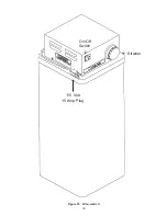
Page 24: ...16 Strainer On Off Switch 115 Volt 15 Amp Plug Ç Å È Figure 10 Fill o matic II ...

Page 25: ...ergent water into the mix container and pump thru the pump andhoses NOTE Do not allow the pump to run dry for more than a few minutes to prevent damage to the pumps components Sanitizing 1 Use a sanitizer mixed according to manufacturers instructions to provide a 100 parts per million strength solution Mix sanitizer in quantities of no less than 2 gallons 7 5 liters of 120 water Allow the sanitize...

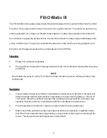
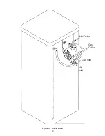
Page 26: ...18 Mix Outlet Gas Outlet Gas Inlet Mix Inlet É Ë Ë Ë Figure 11 Fill o matic III ...

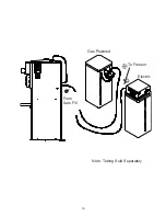
Page 27: ...19 Gas Powered To Freezer Electric From Auto Fill Note Tubing Sold Separately 7 6 ...

Page 28: ......

Page 29: ...en notice of any claimed breach of warranty within the applicable warranty period and c delivers the affected equipment to Stoelting or its designated service location in its original packaging crating also within that period Buyer shall bear the cost and risk of shipping to and from Stoelting s plant or designated service location 4 Extensions The warranty period for deinstallation reinstallation...

Reviews: