background image

6

www.stockmastereurope.nl

Mounting Bracket Assembly

IMPORTANT

To avoid assembly problems follow these instructions exactly.

Step 1 

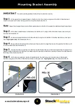
Fit the upper Floor Support Angle to the Mast at A & B as shown using two of the M8 x 20 button head 

screws and nyloc nuts. Screws facing up. Nuts on top. (See illustration No. 1)

Note: 

Upper Floor Support Angle can be fitted upside down on the Mast if required for additional height adjustment.

Step 2

 - 

Fit the Mast Cradle Bracket to the bottom of the Mast at C using an M6 x 16 button head screw and nyloc 

nut. (See illustration No. 2)

Step 3

 - 

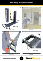
Fix the two Upright Sections to the Base Bracket using four of the M8 x 20 button head screws and nyloc 

nuts. 

Finger tighten only

.

 (See illustration No. 3)

Step 4

 -

  Measure the Vertical Height from the Lower Floor level to the Uppr floor level at the position the Mezz-a-lift 

is to be intsalled. (See illustration No. 4) 

Step 5 

Position the Base Assembly over the Mast Cradel Bracket. Measure the total length from the upper Floor 

Support Angle to the bottom of the Base Assembly. Adjust the position of the base assembly to reflect the measurement 
from Step 4. (See illustration No. 5)

Step 6 

-

 Fix the Base Assembly to the Mast Cradel Bracket, thru the fixing slots on both sides of the Upright

Sections using four of the M8 x 20 button head screws and nyloc nuts. 

Finger tighten only. 

 (See illustration No. 6)

Illustration 1

Illustration 2

B

A

M8 x 20

M6 x 16

C

Summary of Contents for Mezzalift

Page 1: ...CL INST06 Assembly Instructions BEFORE USE see User Instruction Manual Defect as a result of incorrect assembly will not be covered under your product warranty www stockmastereurope nl...

Page 2: ...d then tighten all screws See illustration No 3 Step 4 Lift the Mast as shown cut and remove the Wire Tie then lay the Mast flat on its back again See illustration No 4 Step 5 In the centre of the Mas...

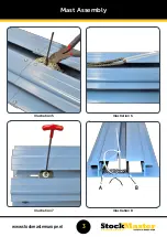
Page 3: ...2 www stockmastereurope nl Illustration 1 Illustration 2 Illustration 3 Illustration 4 M6 x 16 M6 x 16 Mast Assembly...

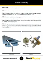
Page 4: ...3 www stockmastereurope nl Illustration 5 Illustration 6 Illustration 7 Illustration 8 A B Mast Assembly...

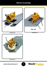
Page 5: ...e Winch Body at 45 degrees so the Chain fits inside the Winch Body See illustration No 3 Step 4 Fix the Winch Mounting Bracket to the Mast at B C using two of the M6 x 16 button head screws and nyloc...

Page 6: ...5 www stockmastereurope nl Winch Assembly Illustration 3 Illustration 4 Illustration 5 B C M6 x 16 E D M6 x 16...

Page 7: ...e Bracket using four of the M8 x 20 button head screws and nyloc nuts Finger tighten only See illustration No 3 Step 4 Measure the Vertical Height from the Lower Floor level to the Uppr floor level at...

Page 8: ...7 www stockmastereurope nl Illustration 3 Illustration 4 Illustration 5 Illustration 6 Mounting Bracket Assembly M8 x 20 M8 x 20...

Page 9: ...he upper landing thru the Floor Support Angle Drill and fix at these locations with appropriate fixings Fixings not supplied See illustration No 1 Step 2 Using a Spirit Level level the Mezz a Lift fro...

Page 10: ...9 www stockmastereurope nl Tighten ALL Fasteners at this point Instalation Illustration 3 B3 B4 B1 B2...

Page 11: ...entre Tie See illustration No 1 Step 2 Position the Chain around the Sprocket using the Large White Wire Tie Once the Chain is engaged correctly cut and remove the Wire Tie See illustration No 2 Step...

Page 12: ...11 www stockmastereurope nl Chain Settting Illustration 3...

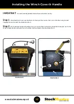
Page 13: ...ver the Winch Fix the top of the cover to the C slots of the Mast using the Self Tapping Screws at A and B See illustration No 1 Step 2 Fix the bottom flange of the Winch Cover at C to the Mast with a...

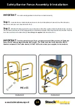
Page 14: ...ge with the M10 x 20mm Patchlok bolts Leave bolts slightly loose See illustration No 1 Note Table Brackets may be fitted in one of two different mounting positions depending on prefered table height S...

Page 15: ...all the way to the bottom of the Mast position the Safety Barrier Fence so it clears the Lift Table on all sides Mark the fixing positions thru the Bottom Flanges in the Safety Barrier Fence Kickrails...

Page 16: ...mbly WARRANTY Thank you for choosing Stockmaster Your safety is in good hands Register your 2 year warranty online at www stockmastereurope nl USER INSTRUCTIONS Before use see the User Instruction Man...

Reviews: