Stockcorner JC-4s Manual Download Page 8

JC-4s manual version 9.1 page  8 
 

        We surely understand that the above antennas 1 & 2 may be difficult to obtain in practice. The 

purpose of the use of a coupler is to be able to operate your transceiver under the worst 
conditions! That’s why we consider acceptable any antenna system that provides adequate wire 
lengths to operate the coupler with the maximum power, if maximum power operation is the 
goal. 

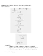
The antennas suggested above demand an artificial ground system to operate. If this is by all 
means impossible to be obtained in our house, we suggest the following types of antennas: 

3.


Unsymmetrical dipole with the longer wire connected to antenna B and the shorter wire to 
antenna "Α" and the antenna switch for antenna “A” operation. (Internal antenna jumper selected 
to “GROUNDED”!) 

4.


G5RV antenna type with open wire feeder (450 Ω) connected as the dipole case above.  (Internal 
antenna jumper selected to “GROUNDED”!) 

We recommend to study the website o

www.pa0fri.com

 and hit “ATU” and read this article about 

the JC-4. A lot of explanation is written there. 
 

Do NOT use a shortened 1:1 balun with a coil 
between the connections A and B!! 

 
In the webshop of Stockcorner we have ready made current baluns available. This baluns are 
produced by our partner Ferrite Applications. The owner is Hugo ON7FU. This balun is specials 
designed for Stockcorner tuners. 
 

5.


   Many users use antenna solutions like an inverted L or even as a sloper. 


G: REMARKS OF TUNER OPERATION 

1.


The closer we use an antenna to its resonant frequency (λ/4), the more power we can apply to it via 
the coupler, because in this condition the coupler is using the least of its components to match the 
antenna and there is no possibility of overheating inductors and capacitors! 

2.


The lower the power we use, the less restrictions apply for the used antenna. This means that 
operating with the standard 100W, any antenna vertical or horizontal from 6 to 60 meters can be 
used.  

3.


The performance of the system depends on the used antenna and counterpoise. The role of the 
coupler ends when the SWR is reduced to the lowest in any case possible level. If at the particular 
frequencies we wish to transmit the SWR is not low enough and going a little up or down in 
frequency almost falls to 1 : 1, we can fix the problem by playing with the length of the antenna.  

4.


In case we face problems, we act as follows: 

We check and fix the counterpoise system. 

We ensure that any wires, cables or metal posts are located far enough from the antenna 
and the directions are perpendicular to the antenna.  

We use another transceiver which is in a good condition to check the system. 


Summary of Contents for JC-4s

Page 1: ...B Grounding of the not used antenna output while operating the other Grounding of both antenna outputs if the 12v DC supply is cut Improved design of the capacitor board version S Improved input SWR during the tuning process version S Improved security When too much RF power during tuning process Tuning will be interrupted Chapters A Before you start B Transceiver Coupler control cable C How is th...

Page 2: ...ual 6 When the 12 volt supply is not connected both antennas outputs are disconnected and grounded So when the tuner is not in use the best possible protection of the coupler and transceiver is obtained 7 During the operation of the tuner the coupler is still protected by a static discharge resistor and 2 x 600V ARC resistors in series B TRANSCEIVER COUPLER CONTROL CABLE 4 x 0 50 mm or better if y...

Page 3: ...ide the tuner So the owner of the tuner can easy make his own design control box to his own demands Just open the small control box and discover how simple the design is The longer wires color RED and BLACK must be connected to your power supply Logical RED is the positive connection Remember that if you do NOT use the same power supply for your transceiver and antenna tuner you must add a jumper ...

Page 4: ...revent RF back into the tuner while using higher powers when used with single wires or verticals In some cases it is better to ground OR to not connect the not used output Example 1 So if you select and tune antenna output A Connect the jumper in de right position and antenna output B will be floating not connected to anything Example 2 So if you select and tune antenna output A Connect the jumper...

Page 5: ...til the LED goes off and then we stop transmitting During this process you can hear all relays fast clicking if you are nearby the coupler If the LED goes off the tune process is finished The SWR must be 1 1 If you push the tune button of the control box and if you do NOT activate your transmitter the led will go off after a few seconds time out If the LED quickly turns on and off at the end of th...

Page 6: ... use them immediately without retuning every time we change them So we have the capability to compare the antennas immediately without having to tune each one of them while the propagation is changing Inside the tuner there are some more jumpers on the top board The 3 pin jumper is for selecting to use the memory function or not Default the jumper is selected to Yes ...

Page 7: ...t some examples 1 Vertical antenna 6 5 meters long without a coil in series or in parallel connected to its base for a better performance in the upper HF bands or 12 meters vertical if we don t care for frequencies higher than 18 Mhz 2 Horizontal wire 25 28 meters or 46 50 meters with a diameter of at least 2 mm and a height about 10m above the ground For a real high performance if we have the ava...

Page 8: ... This baluns are produced by our partner Ferrite Applications The owner is Hugo ON7FU This balun is specials designed for Stockcorner tuners 5 Many users use antenna solutions like an inverted L or even as a sloper G REMARKS OF TUNER OPERATION 1 The closer we use an antenna to its resonant frequency λ 4 the more power we can apply to it via the coupler because in this condition the coupler is usin...

Page 9: ...R AND THE INDUCTORS AND CAPACITORS IN THE COUPLER WILL BE OVERHEATED FOR ANTENNAS 1 3 4 NO GUARANTEE IS GIVEN FOR THE MAXIMUM POWER OF 1KW SSB IF THE USER IS NOT FAMILIARIZED ENOUGH WITH THE SUBJECT THE TYPICAL FORM OF ANTENNA THAT THESE COUPLERS OPERATE IS ANTENNA CASE 2 WE MUST NEVER RETUNE THE COUPLER WITH A LINEAR AMPLIFIER TURNED ON TO OBTAIN LOWER SWR WE MUST NEVER OPERATE THE COUPLER IN THE...

Page 10: ...sceiver must be programmed if needed Or change a switch on the back of the transceiver to disable the internal tuner Read the manual of your transceiver to find this out Remember that the tuner needs to know which output A or B has to be selected So if you still want to switch between A and B you have to add a small switch or force the tuner with PIN 4 tuner side to ground to select output A So YE...

Page 11: ... 02 sec D C supply voltage 11 16 V Maximum supply current 1 2A Typical VSWR in the tuner input 1 2 1 Maximum VSWR in the tuner input 1 6 1 Protection Static discharge NOT FOR THUNDER FALL Dimensions without metal holder Weight 19 5 x 25 x 13 5 cm 2 5 Kg Block schematic overview ...

Page 12: ...JC 4s manual version 9 1 page 12 ...

Page 13: ...designed to match 2 end fed wires in the HF spectrum to a 50 ohm coax cable Use of the JC 4s beyond the specified frequency or power range can destroy it and cause safety risks This product must be considered as a sub assembly intended to be a part of an amateur antenna installation This product is exclusively intended for outdoor use in a fire safe and explosion safe environment ...

Page 14: ...nas or antenna wires during thunderstorms You will find the following High Voltage Hazard symbol on the product indicating that the terminals just like the antenna itself carry dangerous high voltages during transmission and that caution is required in order to avoid electrocution or RF burns You will find the following crossed out wheeled bin symbol on the product indicating that it can harm the ...

Reviews: