JC-4s manual version 9.1 page 10
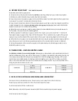
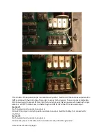
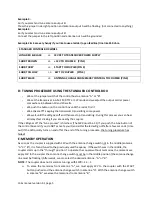
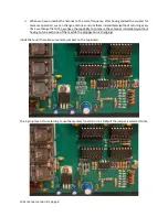
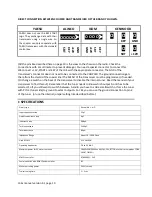
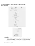
DIRECT CONNECTION BETWEEN COUPLER AND TRANSCEIVER OF THE BRAND YOU OWN.
YAESU
ALINCO
ICOM
KENWOOD
YAESU does not use the KEY-START
logic. They exchange data with their
transceivers using a single wire. So
the coupler can only cooperate with
YAESU transceivers with the standard
control box.
ΟΟΟΟΟ
Ο Ο Ο Ο
Ο
Ο
KEY
Ο
GND
GND
+12V
KEY
SRT
KEY
SRT
+12V
GND
Ο
SRT
Ο
+12V
(All the pins like described here on page 10 is the view to the chassis on the radio. Check the
connections with a multi meter to prevent damage.) You need a special connector to connect this.
We c12V, START and KEY of the JC-4 with the appropriate connector. Τhe GND of the
transceiver’s connector does not need to be connected to the COUPLER. The ground connection gets
there from the shield of the coaxial line! The MENU of the transceiver must be programmed, if needed.
(Or change a switch on the back of the transceiver to disable the internal tuner. Read the manual of your
transceiver to find this out). Remember that the tuner needs to know which output A or B has to be
selected. So if you still want to switch between A and B you have to add a small switch or force the tuner
with PIN 4 (tuner side) to ground to select output A. So YES you can use the ground connection to pin 4
of the tuner. (or use the internal jumper setting like described before)
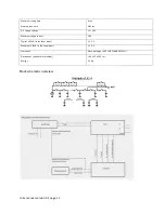
I: SPECIFICATIONS
Circuit type
Reversible L or Π
Input capacitance step
25pF
Output capacitance step
6pF
Inductance step
0.08μΗ
Total capacitance
3400pF
Total inductance
80μΗ
Impedance Range
About 10 – 3000 Ohms
Used RELAYS
32 X OMRON
Operating frequencies
1.6 to 30 ΜΗΖ
Maximum power for 25 meters antenna
1000W SSB (300W on AM, FM, CW, RTTY & all other carrier modes FOR A
SHORT TIME!!! )
ATMEL controller
ΑΤ89C4051 - 24P
Communication with RELAYS and memories
I2C
Maximum tuning power
50 W (carrier)
Typical tuning time
2 – 3 sec.


