


Configuration
ID 441689.03
20
Operating manual Axis switch POSISwitch® AX 5000
7
WE KEEP THINGS MOVING
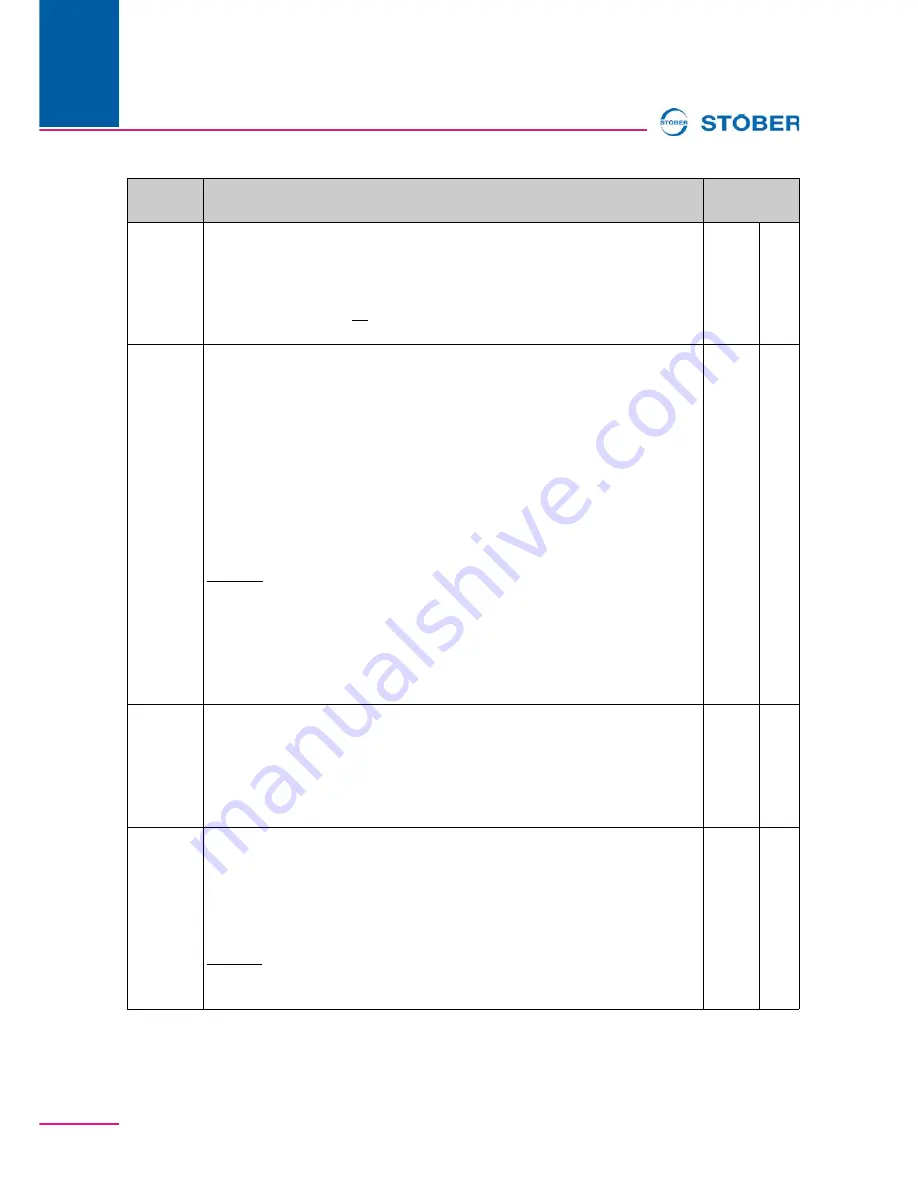
F91
Global
r=2, w=3
Set time axis-switch:
Specifies the set time of the contactor used for the axis
switchover. This time is at least waited before the inverter lets the axis be
electrified.
Value range in ms:0 ...
20
... 32767
Fieldbus: 1LSB=1ms; Type: I16; USS-Adr: 06 16 C0 00
hex
2A5Bh
0h
H08
Axis,
OFF
r=2, w=2
POSISwitch® encoder selector:
Available as an option, the POSISwitch®
control module permits the connection of several motors to one inverter. In
H08
it can be set separately for each of the four (software) axes which connection on
the POSISwitch® (i.e., which motor) is allocated to the particular axis
configuration. This routine permits two or more applications to be run together on
separate (software) axes with a single motor.
NOTE
Following a change in parameter
H08
, correct evaluation of the electronic
nameplate is not ensured until after a device new start.
0: Enc1;
1: Enc2;
2: Enc3;
3: Enc4;
Fieldbus: 1LSB=1; Type: U8; USS-Adr: 08 02 00 00
hex
Only visible when a POSISwitch® was detected on X4.
2E08h
0h
H18
Global,
OFF
read (2)
POSISwitch® port-status:
Indicates as a binary word the POSISwitch® ports
to which encoders are connected. This is determined by the inverter during
startup.
Fieldbus: 1LSB=1; Type: U8; USS-Adr: 08 04 80 00
hex
Only visible when a POSISwitch® was detected on X4.
2E12h
0h
U12
Global
r=3, w=3
Level motor connection:
When the axis switch via POSISwitch® is utilized, the
inverter can test during switching whether the contactor of the motor to be
switched off has actually broken contact (opened). In addition, under certain
circumstances, it can be determined that no motor is connected.
0: inactive;
3: Fault;
Fieldbus: 1LSB=1; Type: U8; USS-Adr: 15 03 00 00
hex
480Ch
0h
Par.
Description
Fieldbus-
address


