26_03_01_0106
270783
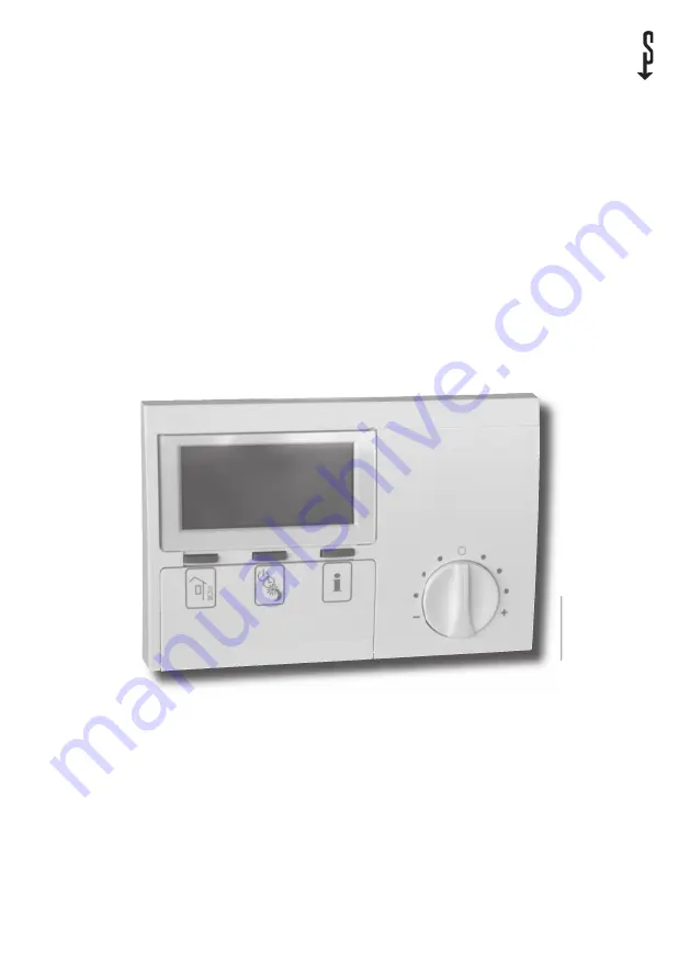
FEK
Control moduleOperating and installation instructions
Page 1: ...26_03_01_0106 270783 26_03_01_0106 FEK Control module Operating and installation instructions...
Page 2: ...1 1 Equipment description 2 1 2 Equipment overview 2 1 3 Important information 2 1 4 Operation 3 1 5 Settings 3 2 Installation instructions 12 for contractors 2 1 Standard delivery 12 2 2 General 12 2...
Page 3: ...control module must only be installed and maintained by quali ed contractors 1 4 Operation The operation is split over three control levels Control levels 1 and 2 are accessible to users and contract...
Page 4: ...erating mode time and day as well as the current room temperature and relative humidity 1 5 1 Operating mode key When connecting a FEK only the operating modes for the pre selected heating circuit are...
Page 5: ...mode 6 Cooling mode 7 Compressor runs 8 Booster in operation Stage 1 2 or 3 9 Fault message flashing 10 BUS connection to the WPMi established 11 WPMI in away mode 12 Standby mode 13 Automatic mode 14...
Page 6: ...you can adjust the heating program The Temperatures parameter enables you to scan the sensor temperatures of the heat pump or heat pump system comparing the actual with the set temperatures the relat...
Page 7: ...emperature Note No display if the corresponding temperature sensor is not connected Room temperature With the Room temp parameters you can adjust the set room temperature for the day and setback mode...
Page 8: ...pump system should heat in day mode Open the control ap At all other times the heat pump operates in setback mode You will already have selected the corresponding set values for day and setback mode u...
Page 9: ...eating circuit 1 and to the mixer flow temperature for heating circuit 2 When adjusting the heating curve the calculated set return or flow temperature which is subject to the outside temperature and...
Page 10: ...peratur C 0 8 Heating curve diagram One heating curve respectively can be adjusted for heating circuit 1 and heating circuit 2 At the factory heating curve 0 6 is set up for heating circuit 1 and heat...
Page 11: ...utside temperature C 20 18 16 14 12 10 8 6 4 2 0 2 4 6 8 10 12 14 16 18 20 Au entemperatur C R cklauf Vorlauftemperatur C 70 60 50 40 30 20 ge nderte Heizkurve 26_03_01_0079 Matching a heating curve t...
Page 12: ...rough curtains or similar External heat influence is prevented e g sun heating system TV set Prevention of direct draughts next to windows and doors For fitting remove the top part of the casing by le...
Page 13: ...ing enables the adjustment of the second digit of the code etc The display shows CODE OK when all four digits have been entered correctly This enables access to control level 3 Closing and re opening...
Page 14: ...scade is formed from weather compensated and room temperature dependent return temperature control In other words the weather compensated return temperature control pre selects the return temperature...
Page 15: ...ngiger Vorlaufsollwert bei A 0 C witterungsabh ngiger Vorlaufsollwert bei A 10 C Raum f hlereinfluss bei K 10 und S 1 2 und Regelabweichung 2 K R R soll R ist 26_03_01_0098 Room in uence Weather compe...
Page 16: ...el eltron hu Internet www stiebel eltron hu Nederland Stiebel Eltron Nederland B V Daviottenweg 36 Postbus 2020 NL 5202 CA s Hertogenbosch 073 6 230000 Fax 073 6 231141 E Mail stiebel stiebel eltron n...