Käyttöohje
User’s manual
7.6. Inputting the rim’s data and balancing with the ALU-3 mode
Follow the instructions in chapter 7.2. to input the rim’s data and press the [MODE] key to enter ALU-1 balancing
mode (Fig 14).
Rotate the wheel by hand, and as the screen says ”RUN ---”, take your hands off the wheel and let it spin. As the
screen says “STOP”, the wheel will stop and the screen will display the data of the wheel’s balance.
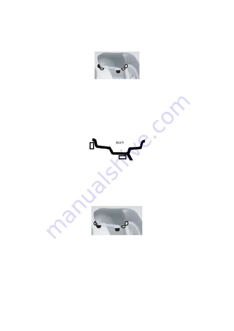
Rotate the wheel slowly. As the inner indicators all light up (10, Fig 3), attach the wheel, weight whose weight is
displayed on the left screen, to the inner edge of the rim to twelve o’clock (Fig 15 left). Rotate the wheel slowly
again. As the outer indicators all light up (11, Fig 3), attach the wheel weight, whose weight is displayed on the
right screen, to the outer edge of the rim to twelve o’clock (Fig 15 right). Rotate the wheel slowly again by hand,
and take your hands off the wheel as the display says “RUN ---”. When the display turns on again, the wheel will
stop and the balancing will be complete.
7.7. Inputting the rim’s data and balancing with the ALU-S mode
The ALU balancing modes described before may not be suitable for all rim structures. The efficiency of the
balancing may also suffer with some rims when using the other ALU modes. In cases like these, it is
recommended to use the ALU-S balancing mode.
Press the [MODE] key until the ALU-S indicator lights up. The balancing mode is displayed in fig 16.
Move the measuring arm to the inner edge of the rim (aI position) as in fig 17, and measure the distance of the
inner side of the rim and press [a+] or [a-] to input the value.
Move the measuring arm further (sE position), measure the value and press [b+] or [b-] to input it.
Measure the inner diameter of the rim (position aI) and press [d+] or [d-] to input the dI value. Measure the outer
diameter (position aE), press [FINE] and [d+] or [d-] to input the dE value.
[38]
Fig 14
Fig 15
Fig 16


