7
Tilt / Roll Adjustment
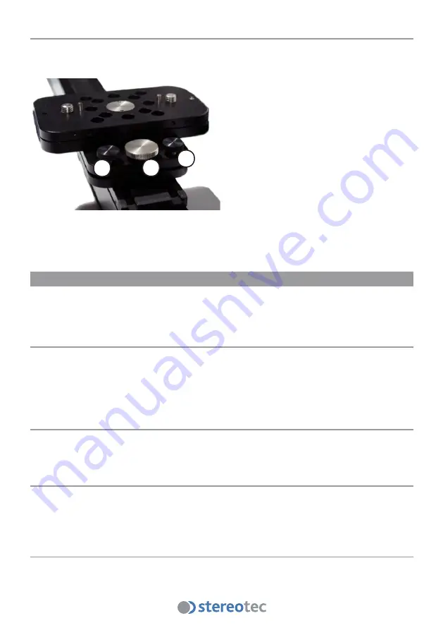
To adjust the tilt and roll angles use the rotary table
(3)
for the camera roll and the fixed table
(5)
for camera tilt.
On each table are three knurled head screws
(a)
,
(b)
. The silver one
(a)
in the middle is for
adjustment, the two black ones
(b)
only for
fixing and safety.
The safety screws
(b)
must be loosen before
adjusting with
(a)
.
For a more acurate 3D-result watch the ste-
reoscopic picture coming from the two cam-
eras, while adjusting.
After the adjustment process tighten the
black safety screws
(b)
.
Hints and Tricks
In most cases the adjustment process is much easier, when the cameras are already con
-
nected and both pictures are viewable as a stereoscopic picture on a stereoscopic screen.
Adjusting Camera Roll
Search for a horizontal line in the scenery e. g. a forest line, a row of houses or even a sky-
line, then aim with the camera-setup on the rig at this line.
While adjusting the camera roll look at the stereoscopic screen. When the lines of both pic
-
tures are parallel the roll angle is adjusted correctly.
Adjusting Camera Tilt
Proceed as same as for the camera roll. Search a line in the scenery and when the lines in
both pictures overlap on the screen the tilt angle is adjusted correctly.
Adjust the Interaxial distance
Now choose the desired interaxial distance between the two cameras. To achieve a more
stereoscopic impression move the two cameras apart.
For nearer objects or less stereoscopic impression move the two cameras together.
Adjust the Angulation / Convergence
After setting up the camera roll, tilt and the interaxial distance, the convergence can be cor-
reted. Just turn the rotary table until the picutres match the focused object.
a
b
b


