background image

INSTRUCTIONS

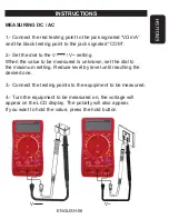
MEASURING DC / AC

1.- Connect the red testing point to the jack signaled “VΩmA”

and the black testing point to the jack signaled “COM”.

2.- Set the dial to the V - - - / V~ setting

When the value to be measured is unknown, set the dial to

the maximum setting. Reduce level by level until reaching the

desired 

one

.

3.- Connect the testing points to the equipment to be measured.

4.- Turn the equipment to be measured on, the voltage will

appear on the LCD display. The polarity will also appear. 

If you want 

to 

hold the value, press the hold button

                  V - - -                                             V~

ENGLISH

ENGLISH-06

Summary of Contents for MUL-052

Page 1: ......

Page 2: ...el selector de funciones est en la escala de Corriente Resistencia o Prueba de diodo Hacerlo puede da ar el medidor y pierde su garant a SIEMPRE descargue los capacitores uniendo sus 2 terminales en e...

Page 3: ...Pantalla digital 2 Posici n de apagado 3 Boton de retenci n de lectura 4 Conector de entrada positivo para medir corriente hasta 10A 5 Conector de entrada positivo para V mA Voltaje alterno continuo...

Page 4: ...angos Voltaje de CA Protecci n contra sobrecarga en rangos de 200mV es protegido en 230V CD CA para otros rangos es protegido en 500V CD o CA Impedancia de entrada 5 Mohm en todos los rangos Rango de...

Page 5: ...undos Medici n de ca da de tensi n 200mV Resistencia Protecci n de sobrecarga 230V CD CA en todos los rangos Rango Resoluci n Precisi n 2m A 1uA 20m A 10uA 200m A 100uA 2A 1m A 1 2 de lectura 2 d gito...

Page 6: ...edir voltaje de CA Si el voltaje a ser medido es desconocido de antemano fije el selector en el rango m s alto posible de la escala y reduzca el rango hasta que la lectura obtenida sea satisfactoria 3...

Page 7: ...Coloque el selector giratorio en la posici n A Si la corriente a medir es desconocido fije el selector en el rango m s alto posible de la escala y reduzca el rango hasta que la lectura obtenida sea s...

Page 8: ...e el selector giratorio en la posici n de Ohms deseada 3 Si la resistencia medida esta conectada a un circuito apague este circuito y descargue los capacitores antes de realizar la medici n 4 Conecte...

Page 9: ...EDICION DE TRANSISTORES hFE 1 Coloque el selector en la posici n de hFE 2 Determine si el transistor es de tipo NPN o PNP y localice el Emisor Base y Colector Inserte las puntas dentro de los agujeros...

Page 10: ...3 Conecte las puntas a los puntos del circuito a ser medido Si la resistencia es menor de 30 Ohms el zumbador buzzer sonar REEMPLAZO DE BATERIA 1 Desatornille la tapa del compartimiento de bater a y...

Page 11: ...0mV a 500V precisi n 0 5 Voltaje ca 200 a 500V precisi n 1 2 Corriente cc 2mA a 10A precisi n de 1 Pantalla de LCD 3 1 2 digitos con indicador de polaridad Temperatura de operaci n 0 a 50 C Humedad re...

Page 12: ...o con el instructivo de uso 3 Cuando el producto ha sido alterado o reparado por personal no autorizado por Electr nica Steren S A de C V El consumidor podr solicitar que se haga efectiva la garant a...

Page 13: ......

Page 14: ...of the multimeter CAUTION when you are working with high voltages NO MEASURE voltages higher than 500V NEVER connect the testing cables to a voltage source if the switch is in the range of Current Re...

Page 15: ...Reading from logic signal CONTROLS 1 LCD screen 2 Off 3 Data hold button 4 10A Jack 5 V mA input jack AC DC Voltage resistance logic signal continuity diodes and Current up 200mA 6 COM jack 7 Testing...

Page 16: ...ge Overload protection At 200mV range it s protected at 230V AC DC current Others are protected at 500V AC or DC Input impedance 5 Mohms on all ranges Frequency range 40Hz to 400Hz ENGLISH ENGLISH 04...

Page 17: ...mV Resistance Overload protection All ranges are 230V DC AC current ENGLISH ENGLISH 05 Range Resolution Accuracy 2m A 1uA 20m A 10uA 200m A 100uA 2A 1m A 1 2 of reading 2 digits 10A 10m A 2 0 of readi...

Page 18: ...en the value to be measured is unknown set the dial to the maximum setting Reduce level by level until reaching the desired one 3 Connect the testing points to the equipment to be measured 4 Turn the...

Page 19: ...e jack signaled COM When measuring up to 200 mA connect the red testing point to the jack signaled 10ADC when measuring up to 10A 2 Set the dial to the A setting 3 Open the circuit and connect the tes...

Page 20: ...t to the jack signaled COM 2 Set the dial to Ohms range 3 If the measured resistance is connected to a circuit turn it off and discharge the capacitors before to measure 4 Connect the testing points t...

Page 21: ...reen in m Volts MEASURING TRANSISTORS hFE 1 Set the dial to the hFE range 2 Determine if the transistor is NPN or PNP and localize the emitter base and collector If you don t know the configuration of...

Page 22: ...led COM 2 Set the dial to the range 3 Connect the testing points on the circuit to be measured If the resistance is less than 30Ohms the multimeter will beep BATTERY REPLACEMENT 1 Unscrew the battery...

Page 23: ...accuracy AC voltage 200 to 500V 1 2 accuracy DC current 2mA to 10A 1 accuracy LCD screen 3 1 2 digits with polarity indicator Operating temperature 0 to 50 C Relative humidity 75 Product design and sp...

Page 24: ...natural days from the day the claim was received 4 Steren sell parts components consumables and accessories to customer as well as warranty service at any of the addresses mentioned later THIS WARRAN...

Reviews: