11
Step 5:
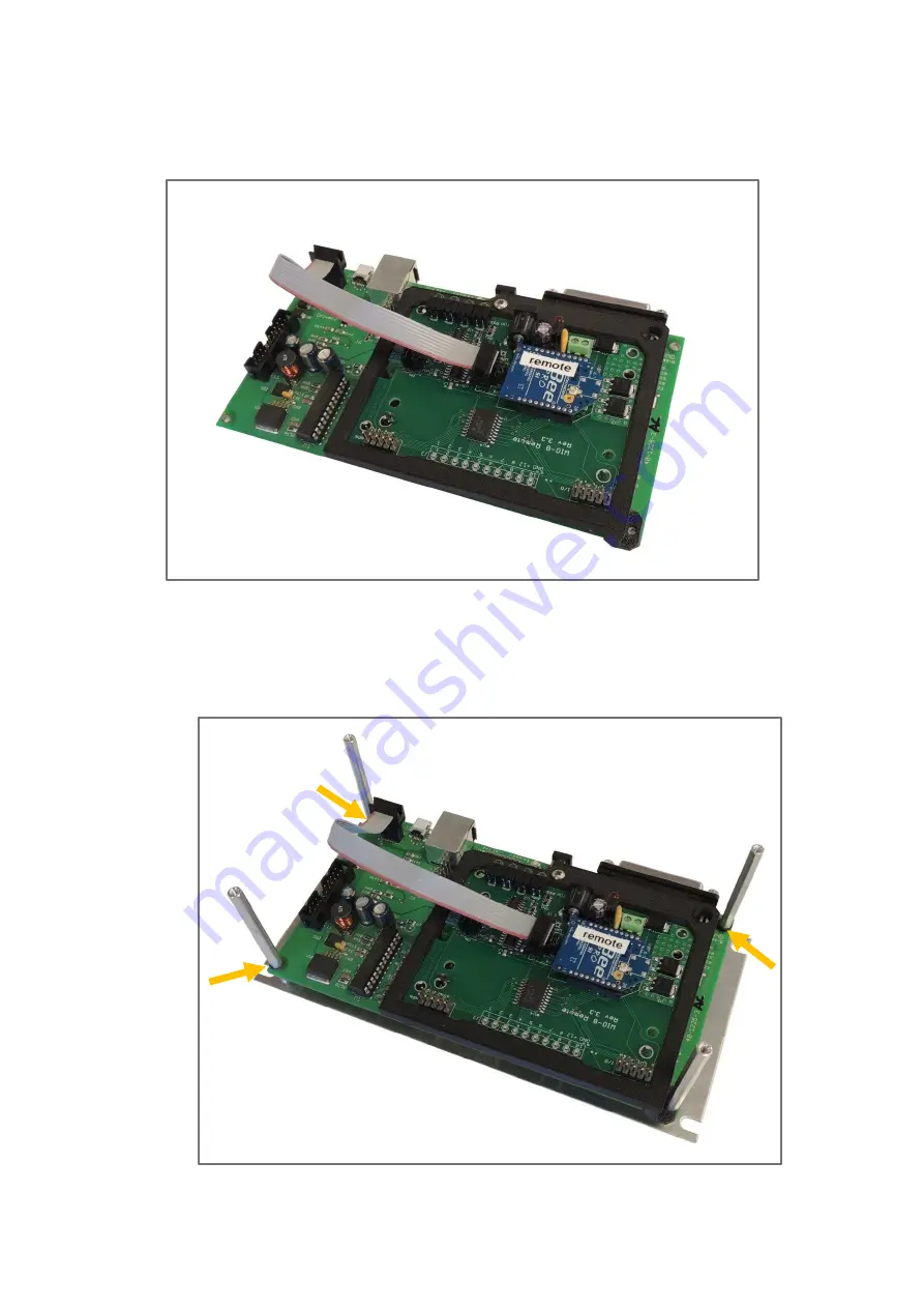
Connect the ribbon cable as shown in Figure 17. The male connector pairs with the female
socket (J7) on the driver board. The other end connects to the Wi-Fi board. Make sure the wire is
oriented the correct direction!
Fig. 17
Ribbon cable installed.
Step 6:
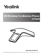
Replace the pan head screws holding the driver board onto the aluminum mounting plate
with the 2-inch hex standoffs. Place washers between the hex standoffs indicated by the arrows
and the driver board as shown in Figure 18.
Fig. 18
Hex standoffs installed.


