-
--
2
2
/
2
1
e
g
a
P
-
--
CUnet Family MKY44-IO32A
Occupied Memory Block
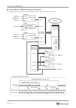
The PWM and Up/Down counter mode of the MKY44-IO32A occupies the MB (Memory Block) of the SA value that is set by SA0
to SA5 of the ST44SW.
In bits 0 to 23 of the MB occupied by the PWM and Up/Down counter mode of the MKY44-IO32A, the value of Counter-0 is stored.
In bits 24 to 31, the status of the general-purpose input pins (Di0 to Di7) is stored. In bits 32 to 55, the value of Counter-1 is stored.
In bits 56 to 63, the status of the general-purpose output pins (Do0 toDo7) is stored.
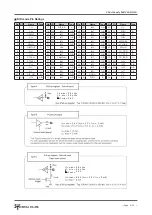
OFF, the latest value loaded in each CUnet cycle
Bit
63 to 56
55 to 32
31 to 24
23 to 0
Content EDo7 to EDo0
Counter-1
Di7 to 0
Counter-0
Bit
15
14
13
12
11
10
9
8
7
6
5
4
3
2
1
0
Content CUT0
15
CUT0
14
CUT0
13
CUT0
12
CUT0
11
CUT0
10
CUT0
9
CUT0
8
CUT0
7
CUT0
6
CUT0
5
CUT0
4
CUT0
3
CUT0
2
CUT0
1
CUT0
0
Bit
31
30
29
28
27
26
25
24
23
22
21
20
19
18
17
16
Content
Di7
Di6
Di5
Di4
Di3
Di2
Di1
Di0
CUT0
23
CUT0
22
CUT0
21
CUT0
20
CUT0
19
CUT0
18
CUT0
17
CUT0
16
Bit
47
46
45
44
43
42
41
40
39
38
37
36
35
34
33
32
Content CUT1
15
CUT1
14
CUT1
13
CUT1
12
CUT1
11
CUT1
10
CUT1
9
CUT1
8
CUT1
7
CUT1
6
CUT1
5
CUT1
4
CUT1
3
CUT1
2
CUT1
1
CUT1
0
Bit
63
62
61
60
59
58
57
56
55
54
53
52
51
50
49
48
Content EDo7 EDo6 EDo5 EDo4 EDo3 EDo2 EDo1 EDo0 CUT1
23
CUT1
22
CUT1
21
CUT1
20
CUT1
19
CUT1
18
CUT1
17
CUT1
16
For the status of the general-purpose input pins
The values read out from Counter-0 and Counter-1 are as follows.
Range of values : 0x000000 to 0xFFFFFF
Initial value : 0x000000 (Right after power-on, hardware reset, and CLR(#CLR0 or #CLR1) signal input)
Overflow operation : MKY44-IO32A continues counting.
Up counter mode : 0xFFFFFF is reset to start recount from 0x000000.
Down counter mode : 0x000000 is reset to start recount from 0xFFFFFF.
Note : You cannot set any values as the initial value of the counter.
Note : When you read the Counter-0 and Counter-1 values using CUnet master, use the hazard protection function of CUnet master.
the digital filter will be stored.


