background image

INSSTE2411014

2

Before installing and operating this product, the owner and/or installer 

must read, understand and follow these instructions and keep them 

handy for future reference. If these instructions are not followed, the 

warranty will be considered null and void and the manufacturer deems 

no further responsibility for this product. Moreover, the following 

instructions must be adhered to in order to avoid personal injuries or 

property damages, serious injuries and potentially fatal electric shocks. 

All  electric  connections  must  be  made  by  a  qualified  electrician, 

according to the electric and building codes effective in your region. 

Do NOT connect this product to a supply source other than 24 VAC and 

do not exceed the load limits specified. Protect the heating system with 

the appropriate circuit breaker or fuse. You must regularly clean dirt 

accumulations on the thermostat. Do NOT use fluid to clean thermostat 

air vent. Do not install thermostat in a wet place. However, installing it in 

isolated walls is allowed.

Note:

When a part of the product specification must be changed to improve operability 

or  other  functions,  priority  is  given  to  the  product  specification  itself.  In  such 

instances, the instruction manual may not entirely match all the functions of the 

actual product.
Therefore, the actual product and packaging, as well as the name and illustration, 

may differ from the manual.
The screen/LCD display shown as an example in this manual may be different 

from the actual screen/LCD display.

warNiNG

Summary of Contents for STE241

Page 1: ...ther information or to consult this guide online please visit our website at www stelpro com S Y S T M E Q U A L I T C ERTIFI REGISTERED Q U A L I T Y S Y S T E M User s Guide STE241 Low voltage elect...

Page 2: ...his product to a supply source other than 24 VAC and do not exceed the load limits specified Protect the heating system with the appropriate circuit breaker or fuse You must regularly clean dirt accum...

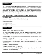
Page 3: ...W at 24 VAC 0 5 A Parts supplied one 1 thermostat two 2 mounting screws Selection of thermostat location The thermostat must be mounted on a wall facing the heating unit at around 1 5 m 5 feet above t...

Page 4: ...r loosen the screw retaining the mounting base and front part of the thermostat Remove the front part of the thermostat from the mounting base by tilting it upward N B The following photos show a conn...

Page 5: ...Stelpro RE 153T electronic thermostat with a 24 VAC transformer and with the second baseboard connected to a Stelpro RE 153 electronic thermostat without a 24 VAC transformer connection example 1 BLAC...

Page 6: ...are used Connection diagrams in this guide are only examples 5 Reinstall the front part of the thermostat on the mounting base and tighten the screw at the bottom of the unit 6 Turn on the power 7 Se...

Page 7: ...the top button to increase the value or the bottom button to decrease it Set points can be adjusted by increments of 0 5 C 1 F To quickly scroll through the set point values press and hold down the b...

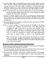
Page 8: ...Day mode 8 hours after being switched to the Night mode For example if you want a night temperature lower than the day temperature both Day Night mode set points will first have to be set at the desi...

Page 9: ...ay with different set points For example if the Single programming mode is activated and the Night mode timer is set at 8 hours the thermostat will be operating in the Night mode for 8 hours at the ni...

Page 10: ...ssible to manually change the Day Night mode during a 24 hour cycle However any manual return to the Night mode will re initialize the Night mode timer to the latest value recorded which modifies the...

Page 11: ...e maintained to ensure frost control Security mode It is possible to impose a maximum temperature set point by activating this mode Then it becomes impossible to exceed this set point regardless of th...

Page 12: ...the adjustment done exit this mode by not pressing down any button for 5 seconds Minimum ON OFF time selection in Long cycle In Long cycle you can adjust the minimum ON OFF time e g the minimum time b...

Page 13: ...Single programming mode was previously deactivated In the opposite case the Day mode is automatically reactivated The Security mode is also reactivated if it was previously activated However the icon...

Page 14: ...y at the electrical panel Check if the heating unit has a switch If so ensure that this switch is turned on The displayed ambient temperature is incorrect Check the presence of an air stream or a heat...

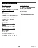
Page 15: ...rature display resolution 0 5 C 0 5 F Temperature set point range 3 C to 30 C 37 F to 86 F Temperature set point increments 0 5 C 1 F Storage temperature 40 C to 50 C 104 F to 122 F Inputs outputs A 3...

Page 16: ...rranty If at any time during this period the unit becomes defective it must be returned to its place of purchase with the invoice copy or simply contact our customer service department with an invoice...

Reviews: