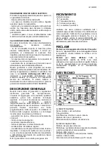
Stel TIG dp 181H Instruction Manual Download Page 11


6918600000


11


c) POWER SUPPLY 
Power  supply  symbol  (number  of  phases  and 
frequency)  
Assigned power supply voltage 
Maximum power supply current 
Maximum effective power supply current (identifies 
the line fuse) 
 
d) OTHER CHARACTERISTICS 
Degree of protection . 
 

INSTALLATION 

WARNING 

This 

Class  A 

equipment is not intended for use in 

residential  locations  where  the  electrical  power  is 
provided  by  the  public  low-voltage  supply  system. 
There  may  be  potential  difficulties  in  ensuring 
electromagnetic  compatibility  in  those  locations, 
due to conducted as well as radiated disturbances. 
This  equipment  does  not  comply  with 

IEC  61000-

3-12

.  If  it  is  connected  to  a  public  low  voltage 

system,  it  is  the  responsibility  of  the  installer  or 
user  of  the  equipment  to  ensure,  by  consultation 
with the distribution network operator if necessary, 
that the equipment may be connected. 
The  good  operation  of  the  Power  Source  is 
ensured  by correct  installation;  you must therefore 
proceed as follows: 
- Position  the  machine  in  such  a  way  that  there  is 
no  obstacle  to  the  air  circulation  ensured  by  the 
internal  fan  since  the  internal  components  require 
suitable cooling. 
-  Ensure  that  the  fan  does  not  send  deposits  or 
dust into the machine. 
- Avoid impacts, rubbing, and – absolutely 
-  exposure  to  dripping  water,  excessive  heat 
sources, or any abnormal situations. 


MAINS VOLTAGE 

The Power Source works at mains voltages 
differing by +/-20% from the rated mains (230V 
rated, Minimum voltage 184V, maximum voltage 
276V).  
TIG dp 181H 


Fuse 16A 


CONNECTION 

- Before making the electrical connections between 
the  current  Power  Source  and  the  line  switch, 
ensure that the switch is turned off . 
-  The  distribution  panel  must  comply  with  the 
regulations in force in the country of use. 
- The mains system must be of the industrial type. 
- Provide a special socket which can receive leads . 
-  For  longer  connecting  cables,  increase  the  lead 
section as required. 
-  Upstream,  the  mains  socket  must  have  a  suitable 
switch provided with delayed fuses. 
- In the event of breakage of the power cable, it must 
be replaced at a qualified assistance centre.  
 

EARTHING 

-  To  ensure  user  protection  the  welding  machine 
must absolutely be correctly connected to the earth 
system 

(INTERNATIONAL 

SAFETY 

REGULATIONS). 
-  It  is  indispensable  to  provide  good  earthing  by 
means of the yellow-green lead in the power cable, 
in  order  to  avoid  discharges  due  to  accidental 
contacts with earthed objects . 
-  The  chassis  (which  is  conductive)  is  electrically 
connected  with  the  earth  lead;  if  the  equipment  is 
not  suitably  connected  to  earth  it  may  cause 
electric shocks which are dangerous for the user.  
 

INSTRUCTION FOR 
INSECURE POSITIONING 

Failure  to  properly  secure  the  machine  can  cause 
personal injury.If machine is in an insecure position 
do not attempt to switch on.Do not put the machine 
on an unlevelled surface greater than 10°. 
 

PREPARING FOR 
ELECTRODE WELDING 
(MMA) 

1)  Follow  the  indications  given  above  for  primary 
connection and installation. 
2) Connect the  earth cable to the  negative pole  of 
the Power Source. 
3) Connect the electrode gun to the positive socket 
4) Press the button 

“SELECT MODE”

 until the led 

N.4 lights up to indicate Electrode Mode. 
5) Insert the bare core of the electrode in the gun. 


PREPARING FOR TIG 
WELDING 

1)  Follow  the  indications  given  above  for  primary 
connection and installation. 
2) Connect the earth cable to the positive socket of 
the machine 
3)  Connect  the  torch  coupling  to  the  negative 
socket of the machine  
4) Connect the torch button coupling to the socket 
provided on the front panel 
5) Connect the gas coupling to the socket provided 
on the front panel  
6)  Connect  the  gas  cylinder  (Argon)  to  the  socket 
provided on the rear panel of the machine.   
7) Press the button 

“SELECT MODE”

 until the led 

Summary of Contents for TIG dp 181H

Page 1: ...000 1 MANUALE DI ISTRUZIONE PER SALDATRICE INSTRUCTION MANUAL FOR WELDING MACHINE BETRIEBSANLEITUNG F R SCHWEI ER TE TIG TIG TIG TIG dp dp dp dp 181H 181H 181H 181H Info www stelgroup com tel 39 0444...

Page 2: ...onized standard in force within the EEA has been used in the design EN 60974 1 Arc welding equipment Part 1 Welding power sources EN 60974 10 Arc welding equipment Part 10 Electromagnetic compatibilit...

Page 3: ...E LA VOSTRA SALUTE Tenere il capo fuori dalla portata dei fumi Provvedere per una ventilazione adeguata dell area di lavoro Se la ventilazione non sufficiente usare un aspiratore che aspiri dal basso...

Page 4: ...denza dei cavi di saldatura I comandi sul pannello frontale consentono una facile programmazione delle sequenze di saldatura in funzione delle esigenze operative La tecnologia inverter usata ha permes...

Page 5: ...enti nel paese di utilizzo L impianto di rete deve essere di tipo industriale Predisporre una apposita spina che preveda l alloggiamento dei conduttori del cavo di alimentazione Per i cavi pi lunghi m...

Page 6: ...TTRODO In Modalit stick Tenere premuto il pulsante SELECT MODE sul pannello frontale della macchina per circa 3 secondi rilasciare poi il pulsante ed eseguire una pressione del pulsante successiva il...

Page 7: ...niche che anticorrosive GAS Il gas di protezione normalmente usato l argon puro con una quantit variabile a seconda della corrente impiegata 4 6 I min SALDATURA TIG DEL RAME Per le propriet gi descrit...

Page 8: ...lettriche assieme ai rifiuti normali In ottemperanza alla Direttiva Europea 2002 96 CE sui rifiuti da apparecchiature elettriche ed elettroniche e relativa attuazione nell ambito della legislazione na...

Page 9: ...ersons PREVENTION OF ELECTRIC SHOCKS Take the following precautions when working with a welding machine keep yourself and your clothes clean do not be in contact with damp or wet parts when working wi...

Page 10: ...sumption excellent dynamic response very high power factor and yields better welding characteristics viewing of the data and of the set functions on the display The electronic components are enclosed...

Page 11: ...ndustrial type Provide a special socket which can receive leads For longer connecting cables increase the lead section as required Upstream the mains socket must have a suitable switch provided with d...

Page 12: ...r about 3 seconds release and press again the same button The Sub Menu LED 22 will blink and the display will show H S Regulate the encoder 13 to change the value of the Hot Start from 0 to Max 50 of...

Page 13: ...th mechanical and anti corrosive GAS The shielding gas normally used is pure argon with a gas flow rate that varies according to the current used and joint set up 4 6 I min TIG WELDING ON COPPER Due t...

Page 14: ...pose of electrical equipment together with normal waste In observance of European Directive 2002 96 EC on Waste Electrical and Electronic Equipment and its implementation in accordance with national l...

Page 15: ...eine entflammbaren Dinge mit sich wie Feuerzeuge oder Streichh lzer Der Lichtbogen kann Br nde verursachen Halten Sie die Spitze der Elektrode von Ihrem K rper sowie von Personen in Ihrer N he fern VO...

Page 16: ...ingem Gewicht und kompakten Abmessungen geringerer Energieverbrauch ausgezeichnetes dynamisches Ansprechen sehr hoher Leistungsfaktor und Wirkungsgrad bessere Schwei eigenschaften Anzeigen der Daten u...

Page 17: ...pannung 230V Mindestspannung 184V H chstspannung 276V Tig dp 181H Sicherung 16A ANSCHLUSS Bevor Sie den elektrischen Anschluss zwischen dem Schwei ger t und dem Leitungsschalter herstellen stellen Sie...

Page 18: ...unktionen 9 Led zur Anzeige des Base Current 2 10 90 10 Led zur Anzeige der GASNACHSTR MUNG 0 1 10 Sek 11 Led zum Einschalten der Pulsfunktion 12 Led zur Anzeige der eingeschalteten Pulsfunktion 13 En...

Page 19: ...m Encoder 13 die 2T oder 4T Funktion w hlen DUTY REGULIERUNG UND PULSFREQUENZ 1 Die Pulsfunktion durch Bet tigen des Druckknopfs 11 w hlen die Led 12 aufleuchtet 2 Den Druckknopf 11 mehrmals bet tigen...

Page 20: ...len beschriebene die Vorbereitung erfolgt ebenfalls wie bereits beschrieben Um die potentielle Oxydation der Schwei stelle zu vermeiden werden Zusatzwerkstoffe mit Phosphor Silizium und desoxydierende...

Page 21: ...lter Board Isolator Side Label Stel Side Label HF generator Board Rear Panel Power Input Cable Power Switch 61320700 64421000 63266000 64436000 66046700 6608120L 61133100 6205770T 61139200 61141500 66...

Page 22: ...IGGER 7 TORCH SWITCH 2 MIN POTENTIOMETER 4 MAX POTENTIOMETER REMOTE CONTROL 5 REG POTENTIOMETER TYPE CONNECTION PIN DESCRIPTION EARTH CLAMP A POSITIVE GAS B GAS TORCH CONN C YES TIG TIG TORCH D NEGATI...

Page 23: ...6918600000 23 WELDING TABLE STEEL...

Page 24: ...6918600000 24 Info www stelgroup com tel 39 0444 639525...

Reviews: