


PRODUCT BRIEF INTRODUCTION
[ 17 ]
PRODUCT BRIEF INTRODUCTION
[ 18 ]
8.3 8 CHANNEL SEPARATE TREBLE,MIDDLE MODE
9.REMOTE INTRODUCTION
10.TECHNICAL FEATURES
POWER SUPPLY
Voltange
9.0-15VDC
Idling current
0,5A
5mm
Switched off with DRC
4mA
Remote IN voltage
6-15 VDC
Remote OUT voltage
12 VDC(130mA)
Switched off without DRC
SIGNAL STAGE
Distortion - THD @ 1kHz, 1V RMS Output
0,0004%
Bandwith @-3 dB
20-22kHz
Master Input
98 dBA
Aux Input
96dBA
Channel Separation @ 1 kHz
90 dB
S/N ratio @ A weighted
Input Sensitivity(Speaker In)
2-15 V RMS
Input Sensitivity(Aux In)
0,2-5 V RMS
Input Sensitivity(Phone)
Input Sensitivity(Speaker In)
10k
Ù
Input Sensitivity(Aux)
22k
Ù
Input Sensitivity(Phone)
Max OUTPUT Level(RMS) @ 0.1% THD
4 V RMS
INPUT STAGE
High Level(Speaker)
FL-FR-RL-RR-SUBL-SUBR,Phone IN
Low level(Pre)
FL-FR-RL-RR-SUBL-SUBR, AUX IN
OUTPUT STAGE
Low level Pre(default)
Midrange(A+B)/Midbass(E+F)/Subwoofer(G+H)
CONNECTION
From/To Personal Computer
1 x USB/B(1.1/2.0) 5M
CROSSOVER N.5(one each output channel)
Filter Type
Full/High/Low Pass /Band Pass
Slope Setting
6/12/18/24/30/42/48 dB
68 steps @ 20- 20kHz
Phase control indepent setting for each channel
0 - 180
Crossover frequency
Subwoofer
Subwoofer
Ground
Ground
Front1/A+B To Midrange
Front1/A+B To Midrange
Subwoofer/G+H To Subwoofer
Subwoofer/G+H To Subwoofer
Hu
Hu
Rem
Rem
12+
12+
+
+
--
ACCU
ACCU
Relay
Relay
R
e
m
O
u
t
R
e
m
O
u
t
4Ch/Power
4Ch/Power
Mid bass
Mid bass
4Ch/Power
4Ch/Power
TW
TW
Midrange
Midrange
Front1/C+D To Tweeter
Front1/C+D To Tweeter
Rear/E+F To Midbass
Rear/E+F To Midbass
1
2
3
4
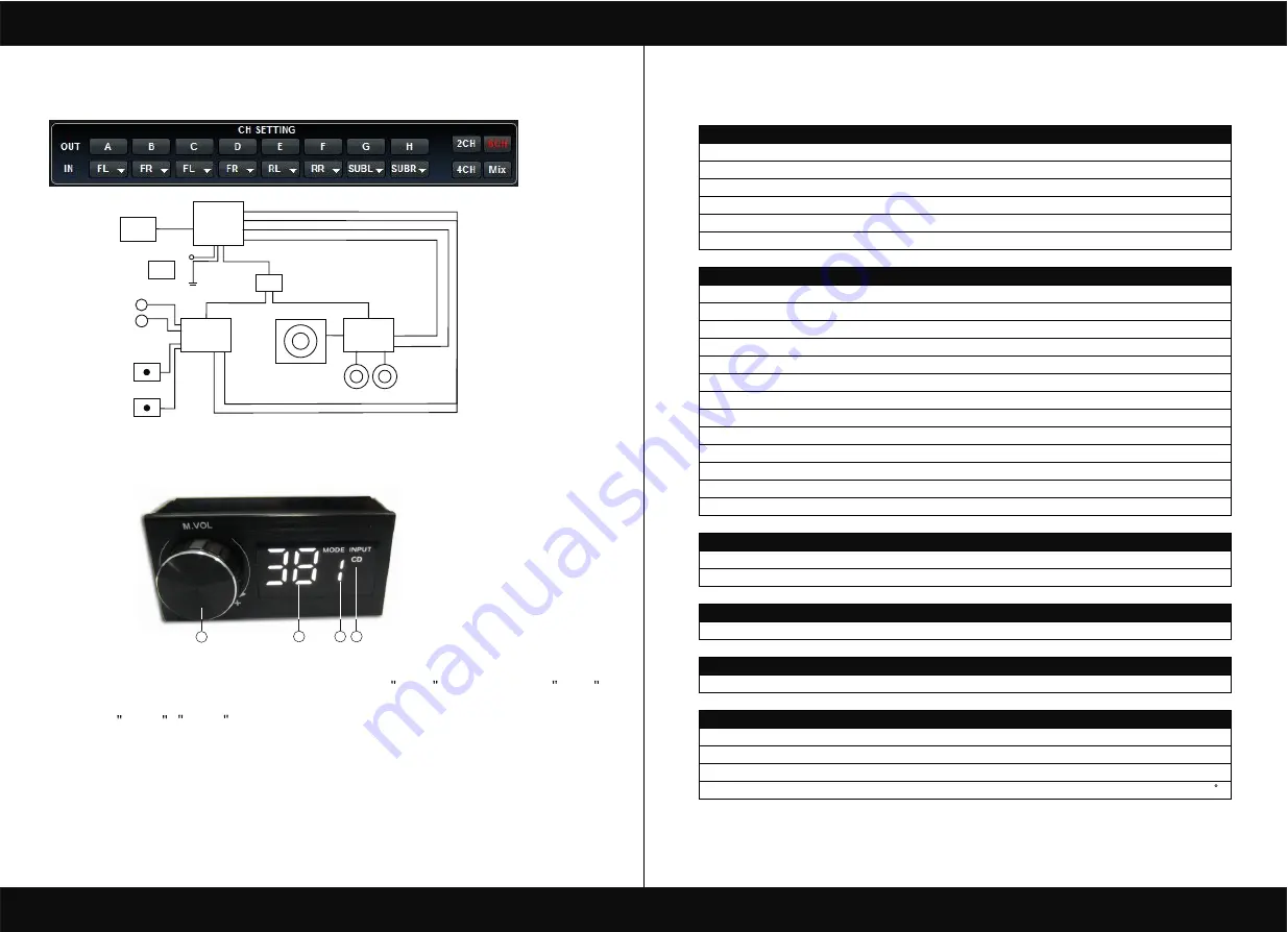
1. A.Main volume.
B.When you press this button for a short time,It is in the MUTE state. And theclose MUTE .
C.When you press this button for a longer time(for a second) ,It will enter the menu mode .
In the MODE or INPUT flishing. You can adjust the mode which you want.
2.Main volume display window.
3.DSP mode display window(1-8).
4.Input display status.(CD.AUX.SPDIF.WIFI).


