background image


SM-S-7 XP Operator’s Manual 

- 12 - 

2017 Version 1.10 

3.


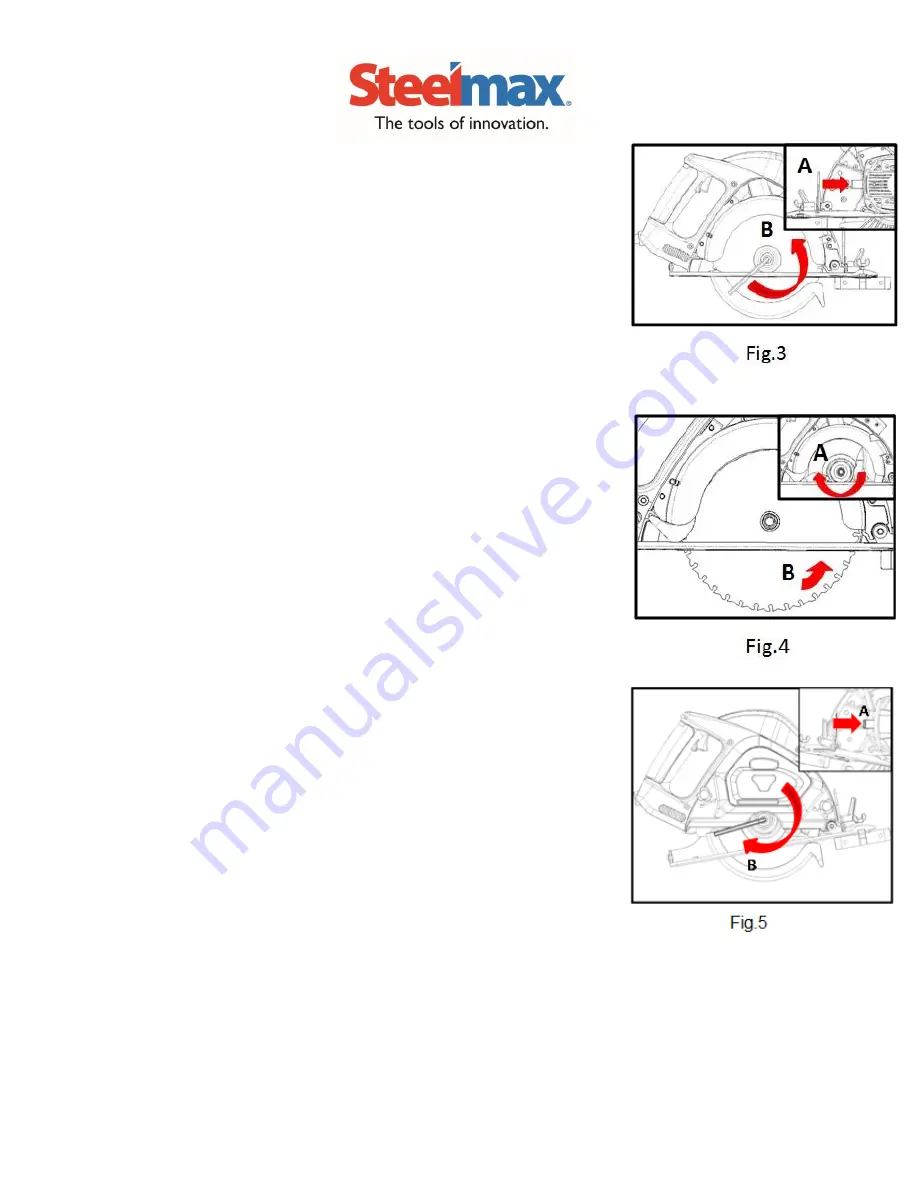
Hold down the shaft lock lever (A) to secure the motor shaft.  Use 
the Allen wrench to loosen the shaft screw (B) (counter-clockwise) 
and remove the shaft screw and flange.  Fig.3 


4.


Open the blade guard (A) and remove old blade.  Align new blade with 
inner  flange  and  install  the  new  blade  and  check  for  proper  blade 
orientation (B).  Fig.4 


5.


Install the outer flange on the blade spindle.  Use the  
the shaft lock lever (A) to secure the motor shaft while tightening the 
shaft screw (B).  Fig.5  
 
Assemble chip shield assembly with blade housing and re-tighten lock 
bolts ((B)

Fig.1 

 
Be sure to repalce Allen wrench for future use. 


Summary of Contents for S-7 XP

Page 1: ...Part Number SM S 7 XP 7 METAL CUTTING CIRCULAR SAW OPERATOR S MANUAL TO REDUCE THE RISK OF INJURY READ AND THOROUGHLY UNDERSTAND THIS OPERATOR S MANUAL Always Wear Eye and Never Place Line Voltage Ear Protection Hands Near Present Cutting Area WWW STEELMAX COM ...

Page 2: ...r other causes not arising out of defects in materials or workmanship This warranty does not apply to machines and or components which have been altered changed or modified in any way or subjected to use beyond recommended capacities and specifications Electrical components are subject to respective manufacturers warranties All goods returned defective shall be returned prepaid freight to Steelmax...

Page 3: ...t Electrical Safety Grounded tools must be plugged into an outlet properly installed and grounded in accordance with all codes and ordinances Never remove the grounding prong or modify the plug in any way Do not use adapter plugs Check with a qualified electrician if you are in doubt as to whether the outlet is properlygrounded If the tool should electrically malfunction or break down grounding pr...

Page 4: ...e and Care Use clamps or other practical way to secure and support the workpiece to a stable platform Holding the work by hand or against your body is u nstable and may lead to l oss of control Do not force tool Use the correct tool for your application The correct tool will do the job better and more safely Do not use tool if switch does not turn it on or off Any tool that cannot be controlled wi...

Page 5: ...enance performed by unqualified personnel could result in a risk of injury When servicing a tool use only identical replacement parts Follow instructions in the Maintenance section of this manual Use of unauthorized parts or failure to follow Maintenance Instructions may create a risk of electric shock or injury and will void the warranty ...

Page 6: ...ep hands away from cutting area and blade Keep your second hand on auxiliary handle or motor housing If both hands are holding the saw they cannot be cut by the blade Keep your body positioned to either side of the saw blade but not in line with the saw blade KICKBACK could cause the saw to jump backwards See Causes and Prevention of Kickback Do not reach underneath the work The guard cannot prote...

Page 7: ...improves the accuracy of cut and reduces the chance for blade binding Always use blades with correct size and shape diamond vs round arbor holes Blades that do not match the mounting hardware of the saw will run eccentrically causing loss of control Never use damaged or incorrect blade washer or bolts The blade washer and bolt were specially designed for your saw for optimum performance and safety...

Page 8: ...orces can be controlled by the operator if proper precautions are taken When blade is binding or when interrupting a cut for any reason release the trigger and hold the saw motionless in the material until the blade comes to a complete stop Never attempt to remove the saw from the work or pull the saw backward while the blade is in motion or KICKBACK may occur Investigate and take corrective actio...

Page 9: ...cal way to secure and support the workpiece to a stable platform Holding the work by hand or against your body leaves it unstable and may lead to loss of control Keep your body positioned to either side of the blade but not in line with the saw blade KICKBACK could cause the saw to jump backwards see Causes and Operator Prevention of Kickback and KICKBACK Make sure nothing interferes with the move...

Page 10: ...SM S 7 XP Operator s Manual 8 2017 Version 1 10 S 7 XP Parts Diagram ...

Page 11: ...d Assembly 1 024 6 SMS7XP 24 6 AC to DC Transformer Modules 1 069 SMS7XP 69 Motor Housing 1 024 7 SMS7XP 24 7 Laser Button 1 070 SMS7XP 70 M5 Panhead Screw Washer 4 024 8 SMS7XP 24 8 Button Switch Assembly 1 071 SMS7XP 71 Set Screw 2 024 9 SMS7XP 24 9 Spring 1 072 SMS7XP 72 Brush Holder 2 024 10 SMS7XP 24 10 Laser 1 073 SMS7XP 73 Carbon Brush 2 024 11 SMS7XP 24 11 O Ring 1 074 SMS7XP 74 Carbon Bru...

Page 12: ... 2 SMS7XP 912 1 SAFETY GOGGLES SMS7XP 911 1 6MM ALLEN WRENCH SMS7XP 83 1 EDGE GUIDE RULER SMS7XP 53 1 CARRYING CASE SMS7XP 901 1 REPLACEMENT CARBON BRUSHES SMS7XP 73 2 WARNING For your own safety never connect the plug to a power source outlet until all assembly steps are complete and you have read and understood the safety and operating instructions The safety cover is attached to the saw for you...

Page 13: ...esigned for metal cutting saws DO NOT USE ABRASIVE WHEELS OR WOOD SAW BLADES ON YOUR METAL CUTTING SAW USE ONLY 7 OR 7 METAL CUTTING SAW BLADES USE OF ABRASIVE WHEELS WOOD SAW BLADES OR SMALLER OR LARGER SAW BLADES WILL VOID YOUR PRODUCT WARRANTY AND MAY RESULT IN PERSONAL INJURY Check that the blade to be used is flat sharp and free of damage or defects 1 Change blade Loosen the lock bolt A and r...

Page 14: ...pen the blade guard A and remove old blade Align new blade with inner flange and install the new blade and check for proper blade orientation B Fig 4 5 Install the outer flange on the blade spindle Use the the shaft lock lever A to secure the motor shaft while tightening the shaft screw B Fig 5 Assemble chip shield assembly with blade housing and re tighten lock bolts B Fig 1 Be sure to repalce Al...

Page 15: ... A adjust the angle plate to the desired bevel angle 0 45 B and re tighten the handle A Fig 6 Laser Guide Use and Adjustment 1 Plug power cord into appropriate power supply and turn on the laser on off switch Laser B will illuminate Fig 7 2 Laser guide automatically follows bevel angle Fig 8 ...

Page 16: ...g the laser guide make sure the saw trigger is not inadvertently engaged Serious injury could result Fig 9 1 Adjusting the laser Use an M2 Allen wrench to tighten or loosen the laser adjustment screw A to adjust the laser beam width Fig 10 2 Use a small flat blade screw driver to align the laser beam with the actual cut line Fig 11 3 Adjust the laser and return zero position by adjusting the guide...

Page 17: ...e back of the saw away from the baseplate until the desired depth of cut is achieved 3 Re tighten the Lock Lever A securely after the depth adjustment is made Fig 14 Saw Trigger Switch Operation Press the stop button A and pull the Trigger Switch B at the same time to start saw motor Saw stops automatically when Trigger Switch is released Fig 15 ...

Page 18: ...f the baseplate and tighten the wing nut to secure it in place at the desired cut width Sighting Notch The sighting notch A near the front of the baseplate provides guidance during free hand cuts When performing cuts the cutting line for the saw blade can be observed via a triangle shaped sighting notch at the front of the base plate Align the cutting line on the workpiece with the triangle shaped...

Page 19: ...SM S 7 XP Operator s Manual 17 2017 Version 1 10 Beware Always keep the saw away from your body when removing the chip shield to avoid spilling chips on your person or clothing The chips can be very hot ...

Page 20: ...been completed make sure power plug has been removed from the receptacle and store it in a secure place out of the reach of children Periodically remove chips in the dust cover and dust from the surface of the power tool with a damp cloth Keep the tool away from water or oil Replacing Carbon Motor Brushes Caution Disconnect plug from power supply before servicing your saw Your saw s carbon motor b...

Page 21: ...ck guard return spring for sufficient tension Replace if spring is weak Check guard for distortion Replace if distorted or damaged 4 Blade Spins on Spindle Check for proper tightness and installation Inspect inner blade flange and outer blade flange for wear or damage Replace if wear is excessive Check flange mating surfaces for flatness Replace if excessive distortion exists Check to ensure flat ...

Page 22: ...nd depth lock for tightness Check for missing teeth bends or cracks in the blade 7 Laser Won t Track Adjust Laser alignment with laser turned on STEELMAX S 7 XP SPECIFICATONS Rated Voltage 120V 60Hz Motor Power 1 560W No Load Motor Speed 3 800 RPM Arbor 20 0 mm Saw Blade Diameter 7 1 4 185mm Weight Gross Net 16 lbs 7 3 kg 12 75 lbs 5 8 kg Max Cutting Depth at 90 ゚ 2 1 2 63 mm Max Cutting Depth at ...

Page 23: ...when using the machine Always keep hands away from the path of the saw blade Always disconnect the plug from the power source before carrying out any work on the machine Never expose tool to rain Laser radiation Avoid direct eye contact with light source Caution When cutting do not touch the metal parts that may become hot Caution Laser radiation do not stare into beam Laser Radiation Caution Labe...

Page 24: ... 2017 Version 1 10 PRODUCT INFORMAITON Thank you for purchasing a Steelmax product Please record the following information and keep this page for your records MODEL S 7 XP METAL CUTTING SAW SERIAL NUMBER PURCHASE DATE PURCHASED FROM ...

Reviews: