background image


Rail Runner Gen III 

Rail Runner Gen III Operator’s Manual 

25 

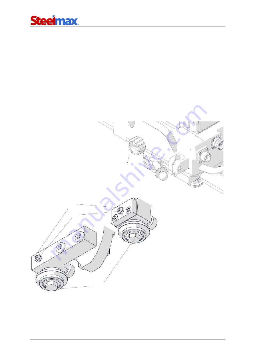
3.8. Adjusting the pressure of rollers 

If  the  resistance  during  the  travel  is  too  little  or  too  much,  loosen  the  knob  (

1

Fig. 13). At the opposite side of the carriage, use the 13 mm and 8 mm flat wrenches 

to loosen the bolts (

2

) and nuts (

3

). Next, use the 2.5 mm hex wrench to adjust the 

screws (

4

), and then tighten the bolts (

2

). 


Move  the  carriage  along  the  track.  If  the  resistance  is  still  incorrect,  repeat  the 

above steps. 


If the carriage moves smoothly, use the 2.5 mm hex wrench to prevent rotation of 

each screw (

4

). Then, use the 8 mm flat wrench to tighten the nuts (

3

). 


Fig. 13. 

Adjusting the pressure of rollers 


Summary of Contents for Rail Runner Gen III

Page 1: ...nnovation 112 Inverness Circle East Suite F Englewood CO 80112 1 87STEELMAX FAX 303 690 9172 www steelmax com sales steelmax com OPERATOR S MANUAL WELDING CARRIAGE R Ra ai il l R Ru un nn ne er r G Ge en n I II II I ...

Page 2: ...ollers 25 3 9 Adapting for seam tracking option 26 3 10 Troubleshooting 30 4 MAINTENANCE 31 5 ACCESSORIES 32 5 1 Seam tracking attachment 32 5 2 Tracking sensor tips 32 5 3 Motorized vertical slide 33 5 4 0 5 m 1 5 ft cable 33 5 5 Hi flex track 34 5 6 Semi flex track 35 5 7 Rigid track 35 5 8 Rack adjustment tool 35 5 9 Contact block 36 5 10 Magnetic units 37 5 11 Semi flex track support 42 5 12 V...

Page 3: ...its to ferromagnetic surfaces that are flat or curved Accessories allow using torches with a larger diameter guiding the carriage on a hi flex semi flex rigid or ring track and tracking the welding seam Using a vacuum track system allows the track to be clamped to surfaces that are non ferromagnetic Two intended configurations are shown in the figure that follows Basic configuration Configuration ...

Page 4: ... your dealer Semi flex tracks OD Minimum 10 m 32 ft Torch type MIG MAG TIG oxy fuel plasma MIG MAG torch diameter 16 22 mm 0 63 0 87 Minimum workpiece thickness for magnetic clamping 5 mm 0 2 Vertical pulling force 315 N 70 lbs Horizontal speed 0 250 cm min 0 98 in min Vertical speed 0 250 cm min 0 98 in min Oscillation type Linear Weld path Straight triangle trapezoid square Oscillation width 0 1...

Page 5: ...mm 12 rack with 180 mm 7 adjustment 1 unit 7 Rack holder 1 unit 8 Clamping block with levers 1 unit 9 Short rod torch holder with clamp 1 unit 10 Cable anchor 1 unit 11 6 mm hex wrench 1 unit 12 6 5 m 21 ft arc ignition cable 1 unit 13 Power cord 1 unit 14 0 5 m 1 5 ft cable 1 unit 15 3 m 10 ft cable 1 unit 16 5 m 16 5 ft cable 1 unit Operator s Manual 1 unit 12 1 3 4 7 8 9 10 11 13 5 6 2 14 16 15...

Page 6: ...Rail Runner Gen III Rail Runner Gen III Operator s Manual 6 1 4 Dimensions 510 mm 20 195 mm 7 7 350 mm 13 8 267 mm 10 5 73 mm 2 9 400 mm 15 7 ...

Page 7: ...n this position Pressing roller Limit switch Drive gear Mounting bracket Carrying handle Rod holder Passive roller Knob to attach the remote control to the carriage Power switch Remote control cable tracking sensor motorized vertical slide connection Display guard Arc ignition socket Power cord Carriage cable connection Front cover ...

Page 8: ...ipment power source cables connections rollers and gear 9 Before each use make sure that no part is cracked or loose Make sure to main tain correct conditions that can have an effect on the operation of the carriage 10 Keep the carriage remote control and other equipment dry Do not expose them to rain snow or frost 11 Keep the worksite well lit clean and free of obstacles 12 Do not use near flamma...

Page 9: ...ield and screen ear protection gloves and protective clothing Do not use loose clothing 26 Do not stop the carriage by hand To stop set the direction switch to O 27 Do not touch moving parts and do not put fingers in the front cover holes 28 Do the maintenance only after you unplug the carriage from the power source 29 Repair only in a service center appointed by the seller 30 If the carriage fall...

Page 10: ...e rails to the surface When working in PC 2G welding position put the rails so that the teeth of the racks point down Fig 1 Connecting the rails and clamping the magnetic units to the surface If a semi flex rail is put on a curve before you attach more rails use the 4 mm hex wrench to loosen the screws of the connecting plates 1 Fig 2 and of the racks 2 Next attach the rails clamp them with levers...

Page 11: ...l Runner Gen III Operator s Manual 11 left 4 to remove the gap 5 between the racks Then tighten the leftmost screw and the rightmost screw of each rack 2 Fig 2 Removing the gap between the racks of a semi flex track 1 2 5 3 4 ...

Page 12: ...smaller diameter you can use brackets 3 But this will decrease the stiffness of the clamping Fig 3 Connecting the supports to the rails Put the workpiece vertically and then put the rails onto the workpiece so that the teeth of the racks point down Next for all rails use the 12 mm hex wrench to set the hinge as shown in Fig 4 Then put the lock pin through the holes 1 and then rotate the wrench 2 t...

Page 13: ... track Use the 13 mm flat wrench to adjust the bolts or the screws by hand until they are in contact with the workpiece 1 Fig 5 Adjust each support equally to make the track concentric to the workpiece Lock the supports with the nuts 2 or levers Fig 5 Attaching the ring track to the workpiece 1 2 2 1 ...

Page 14: ...cillation switch and direction switch to O Pull the lever lock 1 Fig 6 Next set the lever to OFF 2 and loosen the knob 3 fully to move back the gear 4 Then put the carriage so that the mounting brackets are on the rail 5 6 Fig 6 Putting the carriage on a straight track 3 4 Gear moved back 5 Mounting bracket montażowy Mounting bracket 6 1 2 ...

Page 15: ...s into the grooves 2 Tighten the knob 3 to engage the gear of the carriage with the rack of the rail 4 Keep a small backlash between the gear and the rack Move the carriage slightly back and forth to make sure that there is a backlash Fig 7 Engaging the carriage with the track 3 Not engaged Engaged 1 2 2 4 ...

Page 16: ...riage on the track Rotate two roller brackets 2 to put the rollers into the grooves and then set the levers to ON 3 Next move the carriage back and forth to make sure that it moves smoothly Then tighten the screws 1 and use the knob 4 to engage the gear with the rack as described in Positioning on a straight track Fig 8 Rotating the rollers for a curved track 1 2 2 4 3 ...

Page 17: ...track to a stable structure To protect the carriage attach a chain to a carrying handle Make sure that the chains are not loose Use the 0 5 m 1 5 ft cable to connect the remote control to the carriage 1 Fig 9 if the remote control will be put onto the carriage or use the 3 m 10 ft 5 m 16 5 ft cable 2 Then connect the carriage to the power source and put the torch and torch cables into the holders ...

Page 18: ...on socket To do this refer to the diagram from Fig 10 and connect one blue jacketed wire to one terminal of the welding circuit Then connect the other blue jacketed wire to the other terminal of the same circuit To control the second torch connect the green jacketed wires to the terminals of the second welding circuit Fig 10 Connecting the arc ignition cable to welding circuits Make sure that the ...

Page 19: ... of the navigation buttons After you release the button the control system loads and the main screen from Fig 11 shows Fig 11 Control panel with the main screen displayed Tab 1 explains the symbols shown on the right of the main screen Operating mode Arc ignition switch TEST O I Direction switch Forward O Backward F1 F3 F2 Oscillation switch TEST O I Navigation button 2 Navigation button 1 ...

Page 20: ... rotate 0 5 s step 0 1 with tracking off 0 2 5 s step 0 1 with tracking on Oscillation dwell time in right position Press and hold and rotate 0 1 11 8 cm 0 04 4 5 in step 0 1 0 01 Oscillation width Press and release activates and rotate 10 200 cm min 5 78 in min step 5 1 Oscillation speed when the vertical slide is not connect ed Rotate Oscillation speed when the vertical slide is connected Press ...

Page 21: ...on buttons for three seconds to show the first setup screen Fig 12 Fig 12 First setup screen To go to the next setup screen press the right navigation button To go to the previ ous setup screen press the left navigation button Use the knobs to set the required values of parameters Tab 3 Tab 3 Parameters shown on the setup screens Parameter Value Description Method of control Weld path Rotate Trian...

Page 22: ...he move started 2 Set the direction switch to O to travel the carriage back by 10 mm 0 5 in Stitch welding Rotate Off The carriage welds continuously On Activates parameters of stitch welding Do not set them to zero if you want to weld continuously Instead set stitch welding to OFF 0 100 cm 0 40 in step 0 1 Weld length parameter available only when the stitch welding is set to ON Rotate OR 0 100 c...

Page 23: ...atic tracking of the welding seam control of parameter possible only when the tracking sensor is used When Z YZ require the motorized vertical slide or Y is set you can adjust the initial torch position from the main screen with F1 Rotate Off The welding seam will not be tracked automat ically However you can adjust the torch position in the Y axis from the main screen during welding also in the Z...

Page 24: ...s and hold the two navigation buttons for three seconds To control the torch through the carriage set the arc ignition switch to I If the arc ignition switch is set to I the torch starts welding immediately after you select a travel direction Use the direction switch to select a direction of travel Then the travel starts with the set parameters Then the status changes from to You can adjust the pa...

Page 25: ...13 mm and 8 mm flat wrenches to loosen the bolts 2 and nuts 3 Next use the 2 5 mm hex wrench to adjust the screws 4 and then tighten the bolts 2 Move the carriage along the track If the resistance is still incorrect repeat the above steps If the carriage moves smoothly use the 2 5 mm hex wrench to prevent rotation of each screw 4 Then use the 8 mm flat wrench to tighten the nuts 3 Fig 13 Adjusting...

Page 26: ...rent sensor tip use the 2 mm hex wrench and remove the installed sensor rod 4 Next install a sensor rod with fork tip 5 You can also use the 1 5 mm hex wrench to attach one of three tips to a separate rod 6 and then install the rod into the sensor Make sure that the carriage travels in the direction 7 to be able to track the seam correctly Fig 14 Changing the basic configuration to the seam tracki...

Page 27: ...torized vertical slide to the carriage Fig 15 Then use the 0 5 m 1 5 ft cable to connect the sensor to the vertical slide If the vertical slide is not used connect the sensor to the carriage with the 1 m 3 ft cable Fig 15 Connecting the tracking sensor to the carriage 0 5 m 1 5 ft cable 0 8 m 2 6 ft cable ...

Page 28: ... III Operator s Manual 28 Install the torch into the torch holder Then tilt the rod of the sensor against the workpiece so that there is tension in the rod Next put the tip as shown in Fig 16 Fig 16 Setting the tracking sensor correctly ...

Page 29: ...racking system works When the tip of the sensor moves the system senses any small change in position of the seam Then the oscillator the vertical slide and the torch are moved to maintain the correct position above the seam Fig 17 Torch moves with small changes in position of the seam ...

Page 30: ...set to TEST when powering Set the arc ignition switch to O Oscillation switch set to TEST when powering Set the oscillation switch to O Sensor tip fell out of the weld groove when tracking and arcing Set the direction switch to O Make sure that the tension in the rod of the sensor is cor rect Use the correct tip for the application No communication Make sure that all cables are connected correct C...

Page 31: ...iage and the rack of each rail 2 Clean the rollers Make sure that the rollers rotate freely 3 Clean the torch nozzle and replace if damaged Each month 1 Make sure that the knobs and the switches work as intended Replace if they are loose or damaged 2 Examine cables and replace if damaged 3 Tighten screws if loose ...

Page 32: ... 0 5 ACCESSORIES 5 1 Seam tracking attachment Allows the carriage to track the welding seam 5 2 Tracking sensor tips Allow seam tracking in various applications Part number WSP 0523 07 01 13 0 rod required for sensor tips Part number ADT 0506 40 00 00 0 Part number ADT 0506 41 00 00 0 Part number ADT 0506 43 00 00 0 ...

Page 33: ...rized vertical slide Allows the vertical position of the torch to be controlled 5 4 0 5 m 1 5 ft cable Required for connecting the motorized vertical slide to the tracking sensor Part number including 0 8 m 2 6 ft cable OSK 0654 04 00 00 0 Part number PWD 0654 06 00 00 0 ...

Page 34: ... 52 m 5 ft The minimum bend radius is 0 75 m 2 5 ft Use with 8 magnetic units or 8 narrow magnetic units If you need to use more units use narrow magnetic units Use the 13 mm flat wrench to remove the standard rollers and install the rollers for hi flex track Part number rail TRO 0673 00 00 00 0 Part number rollers for hi flex track ZSP 0673 07 00 00 0 ...

Page 35: ... 5 ft The minimum bend radius is 5 m 16 5 ft 5 7 Rigid track Allows guiding the carriage along a straight line The length of a single rail is 2 m 6 5 ft 5 8 Rack adjustment tool Removes the clearance between the racks of two semi flex rails that are put on a curve Part number PKT 0341 13 00 00 0 Part number PRW 0482 15 05 00 0 Part number PRW 0482 47 00 00 0 ...

Page 36: ...om falling off a track with open ends When the carriage comes into contact with the block the limit switch is activated Use two blocks to close the track and limit the travel path to a section Part number for semi flex and rigid track ZDR 0523 76 00 00 0 Part number for hi flex track ZDR 0673 08 00 00 0 ...

Page 37: ...etic unit Heat resistant magnetic unit 100 1200 N 20 C 68 F 20 C 68 F 75 900 N 80 C 176 F 160 C 320 F 50 600 N 120 C 248 F 200 C 392 F Use the 4 mm hex wrench to attach the unit to the tracks as shown in the figures Part number ZSP 0475 44 00 00 0 magnetic unit ZSP 0475 44 00 00 1 heat resistant magnetic unit Part number bracket for hi flex and semi flex track DYS 0482 19 00 00 0 Part number brack...

Page 38: ...Rail Runner Gen III Rail Runner Gen III Operator s Manual 38 M6x20 M6x16 M6x16 M6x35 6 4 6 4 M6x20 M6x16 6 4 ...

Page 39: ...rfaces that differ in height up to 80 mm 3 1 Holding force on a 5 mm 0 2 thick surface Temperature 100 1200 N 20 C 68 F 75 900 N 80 C 176 F 50 600 N 120 C 248 F Install the unit in the same way as the magnetic unit is installed To adjust the angle use the 6 mm hex wrench and loosen four side screws Part number ZSP 0475 85 00 00 0 Part number bracket for hi flex and semi flex track DYS 0482 19 00 0...

Page 40: ...axes of 170 230 mm 6 7 9 1 Holding force on a 5 mm 0 2 thick surface Temperature 100 1200 N 20 C 68 F 75 900 N 80 C 176 F 50 600 N 120 C 248 F Install the unit in the same way as the magnetic unit is installed To adjust the spac ing use the 5 mm hex wrench and loosen four side screws Part number ZSP 0523 19 00 00 0 Part number bracket for hi flex and semi flex track DYS 0482 19 00 00 0 Part number...

Page 41: ...erromagnetic surfaces Holding force on a 5 mm 0 2 thick surface Temperature 100 1000 N 20 C 68 F 75 750 N 80 C 176 F 50 500 N 120 C 248 F Use the 4 mm hex wrench to attach the unit to the tracks as shown in the figures M6x16 M6x16 Part number PDS 0582 10 00 02 0 Part number bracket for hi flex and semi flex track DYS 0582 10 00 00 0 M6x16 M6x16 ...

Page 42: ... use the 17 mm flat wrench not included and set the side screw to ON 5 11 Semi flex track support Allows supporting a semi flex track by using the support instead of a magnetic unit or narrow magnetic unit Use the 4 mm hex wrench to attach the support Part number WSP 0523 12 01 00 1 M6x16 M6x35 ...

Page 43: ... Vacuum track system Allows clamping a hi flex semi flex or rigid track to non ferromagnetic surfaces Part number vacuum pump with safety reservoir AGR 0541 10 10 00 0 115 V UK AGR 0541 10 20 00 0 230 V CEE Other parts of the system are described in a related manual ...

Page 44: ... required Min mm Max mm 200 250 TRO 0523 14 00 00 0 2 4 250 300 TRO 0523 78 00 00 0 2 4 300 350 TRO 0523 20 00 00 0 2 4 350 400 TRO 0523 21 00 00 0 2 4 400 450 TRO 0523 23 00 00 0 2 6 450 500 TRO 0523 24 00 00 0 2 6 500 550 TRO 0523 25 00 00 0 2 6 550 600 TRO 0523 26 00 00 0 2 6 600 650 TRO 0523 22 00 00 0 2 6 650 700 TRO 0523 28 00 00 0 2 6 700 750 TRO 0523 29 00 00 0 2 6 750 800 TRO 0523 30 00 0...

Page 45: ...TRO 0523 52 00 00 0 3 15 1900 1950 TRO 0523 53 00 00 0 3 15 1950 2000 TRO 0523 54 00 00 0 3 15 2000 2050 TRO 0523 55 00 00 0 3 15 2050 2100 TRO 0523 56 00 00 0 4 16 2100 2150 TRO 0523 57 00 00 0 4 16 2150 2200 TRO 0523 58 00 00 0 4 16 2200 2250 TRO 0523 59 00 00 0 4 16 2250 2300 TRO 0523 60 00 00 0 4 20 2300 2350 TRO 0523 61 00 00 0 4 20 2350 2400 TRO 0523 62 00 00 0 4 20 2400 2450 TRO 0523 63 00 ...

Page 46: ...track supports and bracket Ring track support with bolts Part number WSP 0523 14 02 00 0 Ring track support with plastic feet Part number WSP 0523 14 11 00 0 Ring track support with magnets Part number WSP 0523 14 12 00 0 Ring track bracket Part number DYS 0523 14 14 00 0 ...

Page 47: ...2 mm Part number UCW 0476 20 00 00 0 Short rod torch holder with clip 16 22 mm Part number UCW 0476 27 00 00 0 Short low rod torch holder with clip 16 22 mm Part number UCW 0476 06 00 00 0 Long rod torch holder with clamp 16 22 mm Part number UCW 0466 04 00 00 0 Long rod torch holder with clip 16 22 mm Part number UCW 0466 22 00 00 0 ...

Page 48: ... Manual 48 Torch clamp 16 22 mm Part number ZRZ 0466 04 01 00 0 Torch clip 16 22 mm Part number ZCS 0476 06 01 00 0 Torch clamp 22 35 mm Part number ZRZ 0466 19 00 00 0 Short rod Part number WLK 0476 20 01 00 0 Long rod Part number WLK 0466 04 10 00 0 ...

Page 49: ...Rail Runner Gen III Rail Runner Gen III Operator s Manual 49 5 16 Transport attachment Allows transporting the wire feeder Part number PEP 0523 93 00 00 0 ...

Page 50: ...on of MIG MAG torches with the diameter of 16 22 mm 5 8 7 8 Part number ZSL 0497 16 00 00 0 230 V CEE ZSL 0497 16 00 02 0 230 V AU ZSL 0497 16 00 03 0 230 V UK type G ZSL 0497 16 00 04 0 230 V IN type D Part number OSC 0497 01 00 00 0 Part number KLM 0236 00 16 00 0 203 mm rod KST 0525 11 00 00 0 Clamping block ...

Page 51: ...r s Manual 51 Assemble the oscillator with a 203 mm 8 rod and a clamping block 1 Use the 80 mm 3 rod to put the oscillator onto the carriage 2 Next set the switch to the middle position 3 and connect the oscillator to the power supply 4 5 4 1 2 3 5 ...

Page 52: ... 4 ZDR 0523 76 00 00 0 CONTACT BLOCK 1 5 UCW 0476 20 00 00 0 SHORT ROD TORCH HOLDER ASSY 1 5 UCW 0476 27 00 00 0 SHORT ROD TORCH HOLDER WITH CLIP ASSY 1 5 UCW 0466 22 00 00 0 ROD TORCH HOLDER WITH CLIP ASSY 1 6 ZRZ 0466 04 01 00 0 QUICK TORCH HOLDER CLAMP 16 22 1 7 RKJ 000036 HENDLEVER M6 32 5 8 TLJ 0419 04 02 03 0 INSULATION TUBE 1 9 PKT 0466 04 01 10 0 KNOB 1 10 KST 0466 43 04 00 0 DOUBLE CLAMPI...

Page 53: ...SING 1 24 WSP 0523 16 00 00 0 BRACKET 1 25 UCW 0654 02 00 00 0 CABLE ANCHOR 1 26 NKR 000121 KNURLED NUT M6 2 27 TRM 0219 06 16 00 0 CLAMP PLATE 1 28 SKR 0654 99 01 00 0 PLASTIC BOX SERVICE 1 29 PWD 0654 07 00 00 0 PANEL CABLE L 3 M 10 ft 1 30 PWD 0654 08 00 00 0 TRANSMISION CABLE L 5 M 16 5 ft 1 31 KBL 0466 17 00 00 0 ARC IGNITION WIRE L 6 5 M 21 ft 1 32 PWD 0466 16 00 00 0 POWER CABLE 115V 1 32 P...

Page 54: ...W 0523 03 07 00 1 MAGNETIC CLAMP 1 3 PLY 0523 03 01 00 0 BOTTOM PLATE 1 4 NKR 000009 HEX NUT M3 7 5 WKR 000286 HEX SOCKET BUTTON HEAD SCREW M3x6 12 6 MDL 0654 80 05 00 0 CONTROLLER MODULE 1 7 TLJ 000146 HEX SLEEVE M3 12 6 8 MDL 0523 03 03 00 0 PANEL MODULE 1 9 MDL 0523 03 10 00 1 ENCODER MODULE 1 10 PKT 0466 04 01 11 0 TORCH CLAMP KNOB 1 11 OBD 0654 99 02 00 0 HOUSING SERVICE 1 12 RKJ 0523 03 12 0...

Page 55: ... SRB 000401 TORX SOCKET HEAD CAP SCREW M2 5x10 4 15 WZK 0526 02 02 03 0 TRAVEL DIRECTION SWITCH WIRE SET 3 16 WZK 0523 03 13 00 1 NAVIGATION BUTTON WIRE SET 2 17 PKT 000041 KNOOB 3 18 PKR 000055 KNOOB COVER 3 19 OSL 0523 03 14 00 0 PANEL COVER 1 20 ZWS 0523 03 15 00 0 HINGE 2 21 PRS 000111 O RING SEAL 5x1 5 2 22 OSK 0523 03 16 00 0 HINGE AXIS 1 ...

Page 56: ... 3 RKJ 000036 HANDLEVER M6 32 2 4 WKR 000349 HEX SOCKET COUNTERSUNK HEAD SCREW M3x6 16 5 OSL 0654 01 04 01 0 FRONT COVER 1 6 USZ 0654 01 04 02 0 SEAL 1 7 DCS 0654 01 04 03 0 SEAL HOLDER 1 8 OSL 0654 01 04 00 0 FRONT COVER ASSY 1 9 SRB 000074 HEX SOCKET HEAD CAP SCREW M4x8 4 10 SRB 000174 LOW HEAD SOCKET CAP SCREW M5x16 1 11 PLY 0654 01 03 02 0 MOUNTING PLATE 1 12 DCS 0523 02 19 00 0 BELT HOLDER 1 ...

Page 57: ...PRS 000014 INTERNAL RETAINING RING 22w 4 43 PDK 000173 WASHER 8x14x1 4 44 RLK 0341 01 02 01 0 PRESSURE ROLLER 4 45 PDK 000174 WASHER 8x14x0 1 8 46 SRB 000031 FULL THREAD HEX HEAD SCREW M8x30 4 47 SRB 000157 HEX SOCKET HEAD CAP SCREW M8x40 4 48 WSP 0523 01 01 05 0 LEFT BRACKET 1 49 ZDR 0523 01 01 08 0 BUMPER 4 50 SRB 0654 01 01 07 0 BOLT 1 51 SPR 000010 DISC SPRING 6 2x12 5x0 6 2 52 KRP 0654 01 01 ...

Page 58: ... COVER 1 96 WLK 0523 01 02 04 0 DRIVE SHAFT 1 97 PRS 000002 EXTERNAL RETAINING RING 10z 1 98 LOZ 000123 BEARING BALL 2 99 KRP 0523 01 02 02 0 SHAFT BODY 1 100 LOZ 000009 NEEDLE BEARING 10x16x10 1 101 WDZ 0654 01 01 06 0 PISTON ROD 1 102 ZSP 0654 01 01 05 0 MAIN DRIVE ASSY 1 103 PDW 0654 01 01 00 0 CHASIS ASSY 1 104 WZK 0570 01 04 10 0 GROUND WIRE SET 1 105 OSL 0654 01 02 00 0 UPPER HOUSING ASSY 1 ...

Page 59: ... 26 27 28 ITEM PART NUMBER DESCRIPTION Q TY 1 WKR 000330 HEX SOCKET BUTTON HEAD SCREW M4x20 4 2 PLY 0496 96 17 00 0 BOTTOM PLATE 1 3 LOZ 000141 BALL BEARING 8x19x6 2 4 PRW 0523 06 01 20 0 GUIDE RAIL 2 5 SRB 0523 06 01 03 0 SCREW 1 6 KLK 000104 SPRING PIN 2x12 1 7 WKR 000091 HEX SOCKET BUTTON HEAD SCREW M4x8 6 8 OSL 0523 06 01 06 0 COVER 1 ...

Page 60: ...23 06 01 12 1 SENSOR WIRE SET 1 19 PDK 000166 EXTERNAL TOOTH LOCK WASHER 4 3 2 20 SRB 000401 TORX SOCKET HEAD CAP SCREW M2 5x10 10 21 SRB 000063 HEX SOCKET HEAD CAP SCREW M4x14 4 22 SLN 0654 04 01 07 0 MOTOR 1 23 TLJ 000050 HEX SLEEVE M3x8 2 24 MDL 0654 80 04 00 0 Z AXIS MODULE 1 25 OBD 0654 04 01 01 0 HOUSING 1 26 WZK 0654 04 01 12 0 TRANSMISION WIRE SET II 1 27 PKR 000155 SOCKET COVER 1 28 WZK 0...

Page 61: ...NAL TOOTH LOCK WASHER 3 2 12 11 WKR 000286 HEX SOCKET BUTTON HEAD SCREW M3x6 16 12 SRB 000075 HEX SOCKET HEAD CAP SCREW M5x10 2 13 OSL 0654 05 01 02 0 UPPER COVER 1 14 WZK 0523 07 01 11 0 SENSOR WIRE SET 1 15 SRB 000310 HEX SOCKET HEAD CAP SCREW M3x10 4 16 TLJ 0437 05 00 00 0 SLEEVE 1 17 WKR 000042 HEX SOCKET SET SCREW WITH FLAT POINT M4x6 2 18 ELM 0523 07 01 14 0 SENSOR GUIDE 1 19 PRT 0523 07 01 ...

Page 62: ...Rail Runner Gen III Operator s Manual 62 ITEM PART NUMBER DESCRIPTION Q TY 29 RKJ 000036 HANDLEVER M6 32 3 30 KST 0466 43 04 00 0 DOUBLE CLAMPING BLOCK 1 31 PWD 0654 05 02 00 0 TRANSMISION CABLE 1 not shown in the drawing ...

Page 63: ...II Welding Carriage is manufactured in accordance with the following standards EN 60204 1 2006 A1 2009 EN 60974 10 2007 EN ISO 12100 1 2010 and satisfies the regulations of the guidelines 2014 30 EU 2014 35 EU 2006 42 EC 2011 65 EU 2012 19 EU Person authorized to compile the technical file Wiktor Marek Siergiej ul Elewatorska 23 1 15 620 Białystok Poland Białystok 8 September 2020 ________________...

Page 64: ... workmanship under normal use for a period of 12 months from the date of sale This warranty does not cover rollers as well as damage or wear that arise from misuse accident tempering or any other causes not related to defects in workman ship or material Serial number Date of sale Signature and stamp of the seller 0 02 8 October 2020 WE RESERVE THE RIGHT TO MAKE CHANGES IN THIS MANUAL WITHOUT NOTIC...

Reviews: