background image

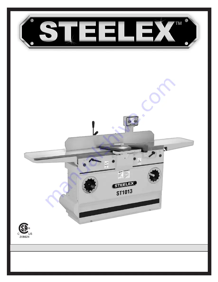
MODEL ST1013 

12" JOINTER

OWNER'S MANUAL

(

For Models Manufactured Since 03/16

)

#18223MN

Phone: (360) 734-3482 • Online Technical Support: [email protected]

COPYRIGHT © MAY, 2016 BY WOODSTOCK INTERNATIONAL, INC. REVISED JUNE, 2018 (HE)

WARNING: NO PORTION OF THIS MANUAL M PPROVAL OF WOODSTOCK INTERNATIONAL, INC.

Printed in China

V2.06.18

Summary of Contents for ST1013

Page 1: ...ince 03 16 18223MN Phone 360 734 3482 Online Technical Support techsupport woodstockint com COPYRIGHT MAY 2016 BY WOODSTOCK INTERNATIONAL INC REVISED JUNE 2018 HE WARNING NO PORTION OF THIS MANUAL M P...

Page 2: ...h defects or other reproductive harm Some examples of these chemicals are Lead from lead based paints Crystalline silica from bricks cement and other masonry products Arsenic and chromium from chemica...

Page 3: ...nded Adjustments 21 Tighten Belt 21 OPERATIONS 22 Overview 22 Stock Inspection Requirements 23 Squaring Stock 24 Surface Planing 25 Edge Jointing 26 Bevel Cutting 27 ACCESSORIES 28 MAINTENANCE 29 Gene...

Page 4: ...wer cord into a grounded outlet 4 Only use this machine to collect wood dust chips never use to collect glass metal liquids asbestos silica animal parts biohazards burning material ashes etc 5 Always...

Page 5: ...Current Rating 15A Minimum Circuit Size 20A Connection Type Cord Plug Power Cord Included Yes Power Cord Length 6 ft Power Cord Gauge 12 AWG Plug Included Yes Included Plug Type 6 20 Switch Type Magn...

Page 6: ...e Movement Type Parallelogram Construction Body Assembly Cast Iron Cabinet Cast Iron Fence Assembly Precision Ground Cast Iron Guard Cast Aluminum Table Precision Ground Cast Iron Paint Type Finish Po...

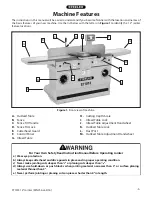
Page 7: ...I Infeed Table Lock J Infeed Table Adjustment Handwheel K Outfeed Table Lock L Dust Port M Outfeed Table Adjustment Handwheel For Your Own Safety Read Instruction Manual Before Operating Jointer a We...

Page 8: ...ight on Page 37 The outfeed table is preset with positive stops so no range of movement is allowed if it gets accidentally unlocked it will not move To adjust the outfeed table positive stops refer to...

Page 9: ...op kid proof DANGEROUS ENVIRONMENTS Do not use machin ery in areas that are wet cluttered or have poor lighting Operating machinery in these areas greatly increases the risk of accidents and injury ME...

Page 10: ...ith moving parts or flying debris Make sure they are properly installed undamaged and working correctly BEFORE operating machine FORCING MACHINERY Do not force machine It will do the job safer and bet...

Page 11: ...is free of nails staples loose knots or other foreign material Workpieces with minor warping should be surface planed first with cupped side fac ing infeed table GRAIN DIRECTION Jointing against the g...

Page 12: ...fuse panel in the building and the machine The power supply circuit used for this machine must be sized to safely handle the full load current drawn from the machine for an extended period of time If...

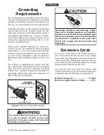
Page 13: ...isk of electric shock The wire with green insulation with without yellow stripes is the equipment grounding wire If repair or replace ment of the power cord or plug is necessary do not connect the equ...

Page 14: ...ZARD Immediately discard all plas tic bags and packing materi als to eliminate choking suf focation hazards for children and animals The Model ST1013 was carefully packed when it left our warehouse If...

Page 15: ...3482 or at techsupport woodstockint com The following is a list of items shipped with your machine Before beginning setup lay these items out and inventory them Note If you cannot find an item on thi...

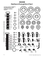
Page 16: ...M APART 5mm 10mm 20mm 15mm 25mm 40mm 30mm 35mm 45mm 50mm 60mm 55mm 70mm 65mm 75mm W A S H ER DIAM E T E R 5 8 W A S H ER DIAM E T E R 9 16 1 2 W A S H ER DIA M E T E R W A S H ER DIA M E T E R 12mm W...

Page 17: ...isposable rags Cleaner degreaser WD 40 works well Safety glasses disposable gloves Plastic paint scraper optional Basic steps for removing rust preventative 1 Put on safety glasses 2 Coat the rust pre...

Page 18: ...nt The physical environment where the machine is operated is important for safe operation and longev ity of machine components For best results operate this machine in a dry environment that is free f...

Page 19: ...uring operation resulting in a machine that runs slightly quieter and feels more solid If the machine will be installed in a commercial or workplace setting or if it is permanently connected hardwired...

Page 20: ...p when exposed to sawdust The fence has a keyway slot built into the underside of it that fits over the key on the table These keep the fence perpendicular to the cutterhead during adjustments Figure...

Page 21: ...to align outfeed table with insert at top dead center When correctly set the insert will barely touch the straightedge as shown in Figure 17 If your outfeed table is correctly set no adjust ments are...

Page 22: ...machine BEFORE understanding its controls and related safety information DO NOT operate or allow others to operate machine until the information is understood DO NOT start machine until all preceding...

Page 23: ...olved with ship ping it is possible some of these adjustments may have changed during transportation and handling Before making any service adjustments we recom mend operating the machine on a trial b...

Page 24: ...usts fence tilt if necessary 4 Adjusts infeed table height to set depth of cut per pass 5 Puts on safety glasses respirator and ear protection 6 Locates push blocks 7 Starts jointer 8 Holds workpiece...

Page 25: ...gum up the cutterhead and produce poor results Remove foreign objects from the workpiece Make sure that any stock you process with the jointer is clean and free of dirt nails staples tiny rocks or any...

Page 26: ...aner Previously Surface Planed Face 2 Surface Plane On a Thickness Planer The opposite face of the workpiece is surface planed flat with a thickness planer see Figure 25 3 Edge Joint On The Jointer Th...

Page 27: ...e entire cut IMPORTANT Keep hands at least 4 away from cutterhead during the entire cut Instead of allowing a hand to pass directly over cutter head lift it up and over cutterhead and safely repositio...

Page 28: ...art jointer 5 Place workpiece firmly against fence and infeed table IMPORTANT To ensure workpiece remains sta ble during cut concave sides of workpiece must face toward table and fence 6 Feed workpiec...

Page 29: ...cally between 1 16 and 1 8 depending on hardness and width of stock 3 Set fence tilt to desired angle of cut 4 Place workpiece against fence and infeed table with concave side face down 5 Start jointe...

Page 30: ...rrent listing of dealers at 1 800 545 8420 or at sales woodstockint com The D3379 Indexable Carbide Inserts Set of 10 measure 14mm x 14mm x 2mm and are the replace ment inserts for the ST1013 Figure 4...

Page 31: ...ic instructions given in this section Note This maintenance schedule is based on average daily usage Adjust the maintenance schedule to match your usage to keep your planer running smoothly Daily Vacu...

Page 32: ...30 ST1013 12 Jointer Mfd Since 3 16 Maintenance Notes DATE MAINTENTANCE PERFORMED...

Page 33: ...at fault 1 Ensure workpiece is suitable for jointing Page 22 2 Reduce feed rate 3 Reduce depth of cut 4 Rotate replace inserts Page 32 5 Clear blockages move machine closer to dust collector upgrade d...

Page 34: ...t collector Fuzzy grain left in workpiece 1 Wood has high moisture content 2 Dull inserts 1 Ensure wood moisture content is less than 20 Allow to dry if necessary 2 Rotate replace inserts Page 32 Long...

Page 35: ...se low pressure compressed air or vacuum nozzle to clean cutterhead pocket 8 Re install insert so that a fresh cutting edge faces outward making sure it is properly seated in cutterhead pocket If all...

Page 36: ...d body as shown in Figure 44 rotate cutterhead if necessary Figure 43 Table positive stop bolts Positive Stop Bolts 5 Place straightedge in positions shown in Figure 45 In each position straightedge s...

Page 37: ...recom mend that you double check the current table posi tions to make sure that they really need to be adjust ed before starting The tables have four eccentric bushings under each corner that allow t...

Page 38: ...sary until outfeed table is parallel with cutterhead Black Lines Represent Straightedge Positions From Overhead View Figure 49 Straightedge positions for verifying if outfeed table is parallel with cu...

Page 39: ...center its highest point during rotation as illustrated in Figures 51 52 3 Loosen outfeed table lock located at front of machine and loosen jam nuts and positive stop bolts located at back of machine...

Page 40: ...in position so it will not move during operation Figure 53 Positive stop bolts for infeed table Top Height Bottom Height Jam Nuts Calibrating Depth Scale To calibrate depth scale 1 DISCONNECT MACHINE...

Page 41: ...nd adjust positive stop bolt until fence is exactly 90 as shown above in Figure 71 To set 45 outward fence stop 1 Raise stop block loosen fence tilt lock and posi tion fence against 45 outward positiv...

Page 42: ...belts onto pulleys and lightly tighten motor bracket fasteners Motor Pulley Approximately 1 4 Deflection Cutterhead Pulley Figure 61 Correct belt deflection when properly tensioned Replacing Belt 1 D...

Page 43: ...3 Visually check alignment of the two pulleys to make sure they are aligned and that V belts are straight up and down see Figure 62 If pulleys are aligned go to Step 7 If pulleys are NOT aligned do St...

Page 44: ...Since 3 16 Electrical Components Figure 64 Motor junction box STOP Reset Switch ON Switch Figure 65 Control panel Thermal Overload Relay To Control Panel To Motor To Power Source Contactor Figure 66...

Page 45: ...Switch Top STOP Reset Switch 2 4 1 3 5 230V MOTOR Start Capacitor 200MFD 250VAC Run Capacitor 20MFD 450VAC 1 3 2 4 5 8 Ground Hot Hot Ground 6 20 Plug As Recommended 220 VAC G BLACK WHITE GREEN RED BL...

Page 46: ...178 179 180 181 182 165 164 164 163 155 135 133 132 131 131 129 128 130 127 126 125 124 122 123 121 117 120 119 118 114 116 115 113 112 108 107 162 161 160 159 158 157 156 154 153 152 151 150 149 148...

Page 47: ...LOCK 122 XST1013122 DRIVER BIT TORX T20 162 XST1013162 LOCK WASHER 10MM 123 XST1013123 12 HELICAL CUTTERHEAD 163 XST1013163 FLAT WASHER 10MM 124 XST1013124 INDEXABLE INSERT 14 X 14 X 2 164 XST1013164...

Page 48: ...OCK WASHER 10MM 203 XST1013203 LOCK WASHER 10MM 213 XST1013213 DEPTH SCALE 204 XST1013204 CAP SCREW M10 1 5 X 35 214 XST1013214 RIVET 2 X 4 205 XST1013205 SHAFT 215 XST1013215 FLAT WASHER 6MM 206 XST1...

Page 49: ...3310 MOUNTING BLOCK 331 XST1013331 CLAMP 311 XST1013311 FLAT WASHER 8MM 332 XST1013332 CAP SCR M10 1 5 X 25 312 XST1013312 HEX BOLT M8 1 25 X 25 333 XST1013333 ADJUSTABLE HANDLE 313 XST1013313 COLLAR...

Page 50: ...0 411 412 413 414 415 1 416 417 418 420 419 421 422 423 424 425 426 427 428 429 430 431 437 436 435 434 433 432 438 439 440 441 442 443 444 445 446 447 450 449 448 415 434 1 404 401 2 401 2 451 402 43...

Page 51: ...1 PH 434 5 XST1013434 5 SWITCH BOX FRONT COVER 415 1 XST1013415 1 KEY 5 X 5 X 45 435 XST1013435 SWITCH PLATE 415 2 XST1013415 2 MOTOR FAN COVER 436 XST1013436 FLAT WASHER 5MM 415 3 XST1013415 3 MOTOR...

Page 52: ...BLACK 505 XST1013505 DECORATIVE STRIPE 511 XST1013511 TOUCH UP PAINT STEELEX TAN 506 XST1013506 READ MANUAL LABEL 512 XST1013512 DISCONNECT POWER LABEL Safety labels warn about machine hazards and ho...

Page 53: ......

Page 54: ...the defect resulted from causes not within the scope of Woodstock International Inc s warranty then the original owner must bear the cost of storing and returning the product This is Woodstock Interna...

Page 55: ...to a friend ______ Yes ______ No 6 What is your age group ______ 20 29 ______30 39 ______ 40 49 ______ 50 59 ______60 69 ______ 70 7 What is your annual household income ______ 20 000 29 000 ______ 3...

Page 56: ...TAPE ALONG EDGES PLEASE DO NOT STAPLE FOLD ALONG DOTTED LINE FOLD ALONG DOTTED LINE WOODSTOCK INTERNATIONAL INC P O BOX 2309 BELLINGHAM WA 98227 2309 Place Stamp Here...

Reviews: