32
742.110 | 14.50
EN
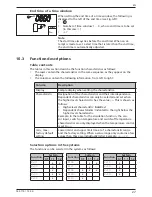
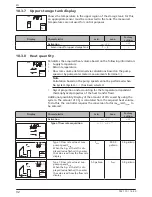
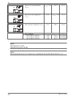
10.3.7 Upper storage tank display
Shows the temperature in the upper region of the storage tank. For this,
an appropriate sensor must be connected to the tank. The measured
temperatures are not used for control purposes.
Display
Characteristic
min.
max.
Factory
setting
Activation
on
,
oFF
oFF
Sensor input for upper storage tank
1 ... 5
–
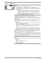
10.3.8 Heat quantity
T
T
F
unc
SET
off
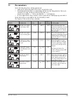
Calculates the acquired heat volume based on the following information:
•
Supply temperature
•
Return temperature
•
Flow rate volume determined via calculations based on the pump
speed or by pulse water meter measurements (terminal
5
).
Note
Calculation based on the pump speed cannot be performed when
No System
(System
0.1
) has been selected.
•
Glycol proportion and accounting for the temperature-dependent
thermophysical properties of the heat transfer fluid.
Additional possibility: Display of the amount of CO
2
saved by using the
system. The amount of CO
2
is calculated from the acquired heat volume.
To do this, the controller requires the conversion factor
Ibs
CO2
/kWh
therm
to
be entered.
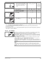
Display
Characteristic
min.
max.
Factory
setting
Activation
on
,
oFF
oFF
F
unc
SET
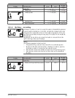
Type of flow rate acquisition
tyP
1
,
tyP
2
1)
–
F
unc
SET
max
Type 1: Flow rate value at max.
pump speed F
max.
.
When the Fig. at the left is dis-
played (value flashes) then enter
the value read from the flow rate
display.
F
min.
999.9
gal/min
0.0 gal/min
F
unc
SET
min
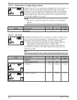
Type 1: Flow rate value at min.
pump speed F
min.
.
When the Fig. at the left is dis-
played (value flashes) then enter
the value read from the flow rate
display.
0.0 gal/min
F
max.
0.0 gal/min
Summary of Contents for TR-A501T-U
Page 47: ...47 742 110 14 50 EN 18 Notes ...
Page 48: ...48 742 110 14 50 EN 742110 ...

