background image


51

4.3


Systems for Supplementary Heating 

4.3.1


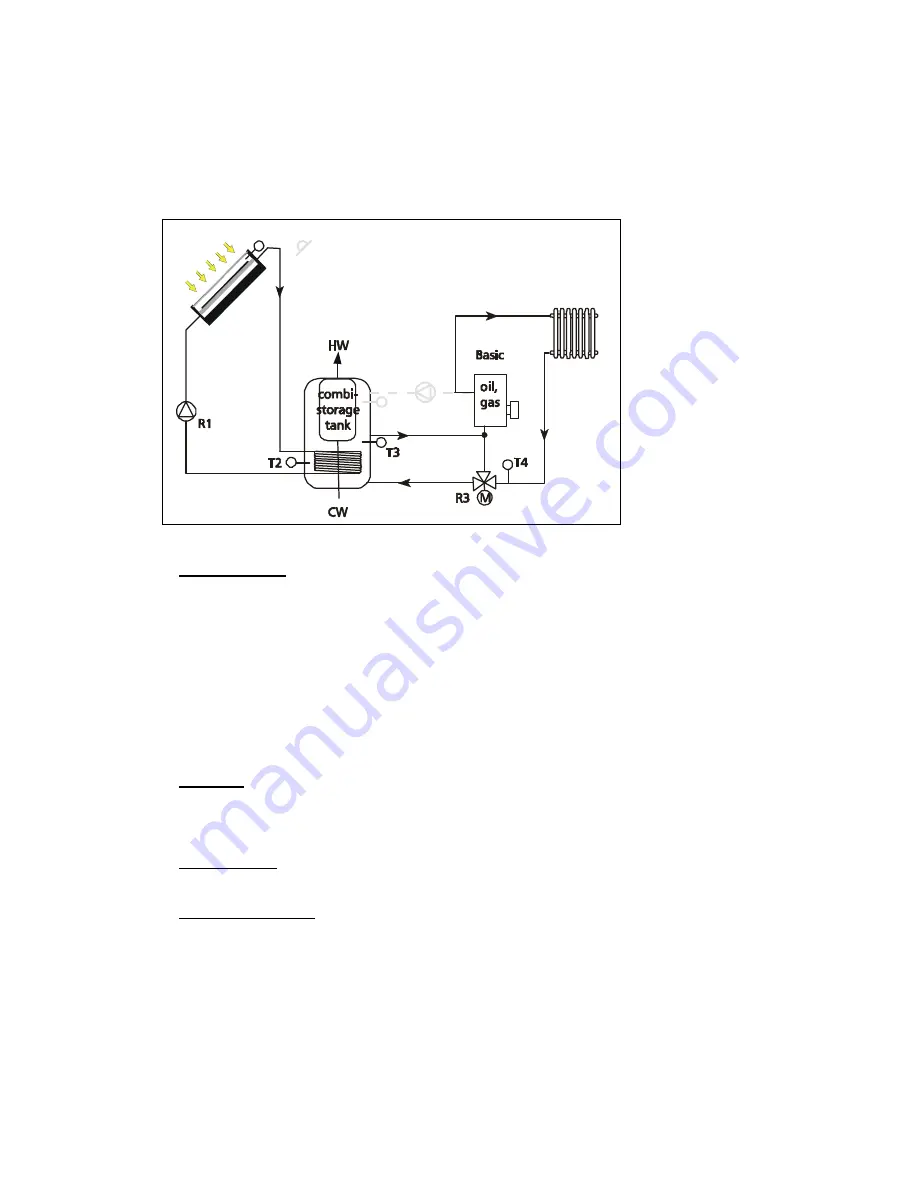
Supplementary Heating with reverse raising, 1 combi storage tank,      

internal heat exchanger 


If, in the 'System 
selection’'
 
menu, the points 
"Supplementary Heating",  
"1 combi tank" and  
"int. heat exchanger" are 
selected, the hydraulic 
diagram illustrated here is 
available for use as a 
basic system (basic) with 
the indicated variants. 


  "Basic" diagram: As soon as the differential temperature between T1 and T2 reaches the set value 

for the switch-on differential temperature (parameter: 'diff. temp. solar ON'), the pump R1 is 
switched on. If the storage tank reaches its maximum storing temperature (parameter: 'storage 
max.') or falls below the switch-off differential temperature (parameter: 'diff. temp. solar OFF'), the 
pump switches off. Depending on the setting (parameter -> speed control -> R1), solar pump’s 
speed control maintains the differential temperature between 'collector' (T1) and 'lower part of the 
storage tank‘(T2) at the value of the parameter 'diff. temp. solar ON' or the absolute temperature of 
the 'collector' (T1) constant at a fixed temperature of 70°C. 
Supplementary heating is provided using the 3-way valve R3 and the sensors T3 and T4. If the 
differential temperature between T3 and T4 reaches the set value (parameter: 'Ret. flow incr. ON') 
the 3-way valve guides the heating return flow above the storage tank. The valve remains in this 
position until the differential temperature falls below the switch-off value (parameter: 'Ret. flow incr. 
OFF') again. 
Definition:  Storage tank is not flown through when the 3-way valve R3 is in a de-energized 
state (no return flow increase)!
 
 
The additional function shown (after-heating) is not activated. 
 

 Add-on 

- AH": R4 and T5 combined with an oil or gas boiler can provide after-heating. A detailed 

functional description of this add-on can be found on page 15. 
 

  "Basic - R" diagram: In some cases the solar circuit pump must be controlled according to the 

solar radiation. For this purpose a radiation sensor S6 must be installed in the collector level. For 
control reasons T1 must be inserted between the collector and storage tank. A detailed functional 
description of this add-on can be found on page 15. 


To prevent erroneous settings, the described switch-on and switch-off values are interlocked, 
this means they can be set only at a specific value to one another. 


R4

Basic-AH

T1


or S6 (radiation sensor) for Basic-R

T5

Summary of Contents for TR 0704

Page 1: ...Thermal Systems 7 inputs 4 outputs 709 756 Z02 08 08 nderungen aufgrund technischer Verbesserungen vorbehalten EN These operating instructions are part of the product Read these operating instruction...

Page 2: ...ate Time Menu 11 3 6 Clocks Menu 11 3 7 System Selection Menu 11 3 8 Functions Menu 11 3 9 Links Menu 12 3 10 Extras Menu 12 3 11 Manual Operation Menu 12 4 SYSTEM SELECTION 13 4 1 Systems with Intern...

Page 3: ...ating 67 7 4 Solid Fuel Boilers 68 7 5 Recharging Storage Tanks 69 7 6 Swimming Pool Heating 70 7 7 Bypass in the Solar Circuit 71 8 CONFIGURATION 72 9 SYSTEM EXPANSION 72 9 1 IS Bus 73 9 2 RS 232 73...

Page 4: ...a controller for thermal solar systems for feeding solar heat into a water or buffer store For the installation of the other components such as the solar collectors pump group and the storage basins p...

Page 5: ...only be carried out by trained electricians The regulator is protected against overcharging and short circuiting 2 1 Location of installation The controller is designed for installation on vertical w...

Page 6: ...ies as described here are only possible when the terminal box cover plate of the controller is open For this purpose clear the power supply net Stick to all valid regulations for working on a cleared...

Page 7: ...fig 6 Radiation sensor connection Pulse generators If pulse generators are used with a reed switch the connection polarity is arbitrary Ensure the correct polarity when using an open collector circuit...

Page 8: ...unctions must be linked 3 2 Measuring Values Menu All measuring values recorded by the regulator are displayed in the Measuring values submenu After opening the menu the current measuring values are l...

Page 9: ...them is displayed by a pump symbol The pump symbol does not move in a current less state If an output is active the corresponding symbol rotates The status or error display provides information on whi...

Page 10: ...ronic relays for the speed control of circulating pumps The speed control can be separately activated or deactivated for each of these outputs Both speed controls are activated as a factory setting If...

Page 11: ...re available After being opened the menu window only shows the clocks used under Functions If thus far no time functions have been activated this menu window can not be opened Each clock can be progra...

Page 12: ...ly set Press the OK button for 2 seconds with delete records to delete the measuring value records saved to date see chap 3 3 For confirmation ok appears until the menu is exited 3 11 Manual Operation...

Page 13: ...onal system planning The system regulator provides these system groups in a basic version Basic and with different add ons Ci AH SFH CZ R These add ons are explained in more detail in the following Ci...

Page 14: ...ng parameters after heating OFF or AH extern threshold are also factored in by the switch valve s control Systems with after heating AH can only be switched to the upper charging zone when the chargin...

Page 15: ...the two after heaters are not activated Add on Ci Output R2 and the T4 temperature sensor can also provide a control of a circulation pump for the warm water cycle A detailed functional description o...

Page 16: ...rage max 60 C Date Time collector max 130 C Clocks Diff temp solar ON 8K Service Diff temp solar OFF 4K OK OK Menu 2 sec speed control System selection intern heat exchanger Functions OK Links 1storag...

Page 17: ...ial temperature parameter diff temp solar OFF If this is the case the solar circuit pump and the switch valve are switched off Definition When the 3 way valve is switched off the collector array 1 is...

Page 18: ...ked this means they can be set only at a specific value to one another Connecting diagram Menu navigation here for the scheme Basic V OK Measuring values collector 1 C Operating status collector 2 C S...

Page 19: ...temperature between collector T1 or T2 and lower part of the storage tank T3 constant at the value of the parameter diff temp solar ON or the absolute temperature of the collector T1 or T2 constant at...

Page 20: ...bottom C OK OK solar pump1 h Parameter storage max 60 C solar pump1 h Date Time collector max 130 C solar pump2 h Clocks Diff temp solar1 ON 8K solar pump2 h Service Diff temp solar1 OFF 4K OK OK Menu...

Page 21: ...arged again For this purpose the solar circuit pump is deactivated for a short period storage tank priority Test period If the priority storage tank reaches its switch on temperature within this perio...

Page 22: ...s storage 2 bottom C OK OK solar pump h Parameter storage 1 max 60 C solar pump h Date Time storage 2 max 60 C reversing valve h Clocks collector max 130 C reversing valve h Service Diff temp solar ON...

Page 23: ...charged the prioritized storage tank is checked at regular intervals storage tank priority Test interval if it can be charged again For this purpose the solar circuit pump is deactivated for a short...

Page 24: ...solar pump1 h Date Time storage 2 max 60 C solar pump2 h Clocks collector max 130 C solar pump2 h Service Diff temp solar ON 8K OK OK Menu 2 sec Diff temp solar OFF 4K System selection intern heat exc...

Page 25: ...od storage tank priority Test period If the prioritized storage tank reaches its switch on temperature within this period it will be charged again When the storage tank is charged the option of switch...

Page 26: ...collector 1 C Operating status collector 2 C Settings storage 1 bottom C OK OK storage 2 bottom C Parameter storage 1 max 60 C solar pump h Date Time storage 2 max 60 C solar pump h Clocks collector...

Page 27: ...this will be charged again When a storage tank is charged it is also checked if the switch on differential temperature of the passive collector array is reached If this is the case the pump of the pas...

Page 28: ...C Operating status collector 2 C Settings storage 1 bottom C OK OK storage 2 bottom C Parameter storage 1 max 60 C solar pump1 h Date Time storage 2 max 60 C solar pump1 h Clocks collector max 130 C s...

Page 29: ...solar circuit pump is deactivated for a short period storage tank priority Test period If a storage tank with higher priority reaches its switch on temperature within this period this will be charged...

Page 30: ...om C Parameter storage 1 max 60 C solar pump h Date Time storage 2 max 60 C solar pump h Clocks storage 3 max 60 C reversing valve 1 h Service collector max 130 C reversing valve 1 h OK OK Menu 2 sec...

Page 31: ...e tank is charged it is checked at regular intervals storage tank priority Test interval whether a storage tank with higher priority can be charged again For this purpose the solar circuit pump is dea...

Page 32: ...orage 2 max 60 C solar pump1 h Clocks storage 3 max 60 C solar pump2 h Service collector max 130 C solar pump2 h OK OK Menu 2 sec Diff temp solar ON 8K solar pump3 h System selection intern heat excha...

Page 33: ...torage tank with higher priority can be charged again For this purpose the solar circuit pump is deactivated for a short period storage tank priority Test period If a storage tank with higher priority...

Page 34: ...60 C storage 3 bottom C Date Time storage 2 max 60 C solar pump h Clocks storage 3 max 60 C solar pump h Service collector max 130 C valve collector h OK OK Menu 2 sec Diff temp solar ON 8K valve coll...

Page 35: ...it pump is deactivated for a short period storage tank priority Test period If a storage tank with higher priority reaches its switch on temperature within this period this will be charged When a stor...

Page 36: ...ttom C Date Time storage 2 max 60 C solar pump1 h Clocks storage 3 max 60 C solar pump1 h Service collector max 130 C solar pump2 h OK OK Menu 2 sec Diff temp solar1 ON 8K solar pump2 h System selecti...

Page 37: ...condition of a storage tank with lower priority is met the 3 way valves are switched to charge the corresponding storage tank When a secondary storage tank is being charged it is checked at regular in...

Page 38: ...ks storage 3 max 60 C solar pump1 h Service storage 4 max 60 C reversing valve 1 h OK OK Menu 2 sec collector max 130 C reversing valve 1 h System selection intern heat exchanger Diff temp solar ON 8K...

Page 39: ...switch on condition of a storage tank with lower priority is met the corresponding solar circuit pump is switched on and the storage tank is charged until its switch off criteria storage tank y max o...

Page 40: ...C solar pump1 h Clocks storage 3 max 60 C solar pump1 h Service storage 4 max 60 C solar pump2 h OK OK Menu 2 sec collector max 130 C solar pump2 h System selection intern heat exchanger Diff temp sol...

Page 41: ...the maximum storing temperature parameter storage max is reached or falls below the switch off differential temperature of the solar circuit parameter diff temp solar OFF To protect the charging circu...

Page 42: ...setting Connecting diagram Menu navigation here for the scheme Basic OK Measuring values collector C Operating status storage bottom C Settings charging temp C OK OK charge pump h Parameter storage ma...

Page 43: ...g temperature parameter storage tank x max is reached or falls below the switch off differential temperature of the solar circuit parameter diff temp solar OFF To protect the charging circuit from ove...

Page 44: ...Menu navigation here for the scheme Basic OK Measuring values collector C Operating status storage 1 bottom C Settings storage 2 bottom C OK OK charging temp C Parameter storage 1 max 70 C charge pump...

Page 45: ...lls below a value of 3 Kelvin The solar circuit pump R2 remains active until either the maximum storing temperature parameter storage tank x max is reached or below the switch off differential tempera...

Page 46: ...C Settings storage 2 bottom C OK OK storage 3 bottom C Parameter storage 1 max 70 C charging temp C Date Time storage 2 max 70 C charge pump h Clocks storage 3 max 70 C charge pump h Service collecto...

Page 47: ...rging temperature is reached Important The control device for the fresh water function is not linked in the diagram This must be activated in the menu Service Functions Fresh water at R2 Settings The...

Page 48: ...n the objective is absolute temperature this control objective has been saved both in the settings Absolute temp and also Differential temp The control devices are therefore dependent on this setting...

Page 49: ...ating the solar circuit is deactivated when T3 is only 3 Kelvin below the maximum charging temperature parameter Max charging temp If the charging circuit continues to heat up because of an erroneous...

Page 50: ...locks Diff temp solar ON 8K storage 2 bottom C Service Diff temp solar OFF 4K charge pump 1 h OK OK Menu 2 sec charging temp 1 max 115 charge pump 1 h System selection plate heat exchanger charging 1...

Page 51: ...tary heating is provided using the 3 way valve R3 and the sensors T3 and T4 If the differential temperature between T3 and T4 reaches the set value parameter Ret flow incr ON the 3 way valve guides th...

Page 52: ...e Time collector max 130 C solar pump h Clocks Diff temp solar ON 8K reversing valve h Service Diff temp solar OFF 4K reversing valve h OK OK Menu 2 sec return flow incr ON 4K System selection supplem...

Page 53: ...FF To protect the charging circuit from overheating the solar circuit is deactivated when T3 is only 3 Kelvin below the maximum storing temperature parameter Max charging temp If the charging circuit...

Page 54: ...ttings charging temp C OK OK storage top C Parameter storage max 70 C storage middle C Date Time Diff temp solar ON 8K heating return flow C Clocks Diff temp solar OFF 4K charge pump h Service chargin...

Page 55: ...s checked at regular intervals storage tank priority Test interval whether the priority storage tank can be charged again For this purpose the solar circuit pump is deactivated for a short period stor...

Page 56: ...e 2 max 60 C storage pump1 h Clocks Diff temp solar ON 8K storage pump1 h Service Diff temp solar OFF 4K storage pump2 h OK OK Menu 2 sec return flow incr ON 4K pump storage2 h System selection supple...

Page 57: ...ess the OK button for 2 seconds The most important Settings of each activated thermostat can be customized Most importantly in addition to selecting the required temperature input and output to be con...

Page 58: ...e progression The inputs E1 regulator to E7 regulator are available on the regulator or the inputs E1 IOBox to E4 IOBox are available on each of the four possible add on units for additional IO boxes...

Page 59: ...only installed in the collector line the measured collector temperature is often far below the real pipe temperature when the pumps are stationary Due to their high efficiency the collector can howev...

Page 60: ...w rate display is restricted to 50 000l This resets to 0 liters not after 99 999 l but after 50 000 l The sensor inputs E1 regulator to E7 regulator for temperature and flow rate values are available...

Page 61: ...ctivate the DVGW heating in the menu Settings Service Functions DVGW heating by pressing the OK button for 2 seconds Note When setting the temperature it must be ensured that this temperature can also...

Page 62: ...t protection the collector can be kept at the required temperature with the heated storage tank water If it falls below a frost protection temperature of 4 C on the set sensor sensibly collector senso...

Page 63: ...ume flowing in the hot water line at a constant temperature Functions Fresh water at R2 aim temperature x C at the extraction points If the temperature at Supply line st upp falls below the value for...

Page 64: ...temperature is reached So the link must be changed so there is the following linguistically formulated logic Switch R3 regulator on if the System control wants to switch on and the Time function 1 wan...

Page 65: ...be defined more precisely by linking it with other functions Possibilities for example include a temporal link using a time clock or an additional query of the storage tank temperature These function...

Page 66: ...4 To still be able to ensure a specific basic temperature in the storage tank and therefore a minimum level of comfort a thermostat function chapter 5 1 must also be programmed For implementing you do...

Page 67: ...he help of a differential thermostat To enable supplementary heating you need only one of the four differential thermostat functions chapter 5 2 two available inputs and an available output called Tx...

Page 68: ...boiler If the boiler exceeds its set Max or Min limit the circulating pump will also switch off Implementation Open the menu item Settings Service Functions thermostats and activate three or to upgrad...

Page 69: ...ump Rx is activated and heat is therefore recharged from storage tank Y to X Depending on the type of individual storage tanks this recharging can be done directly or via a heat exchanger Implementati...

Page 70: ...e swimming pool has reached its switch off temperature or if the plate heat exchanger no longer provides a sufficient temperature level the pump is deactivated again If the temperature sensor Tx is in...

Page 71: ...e until the morning then only the collector will have been heated In the pipelines however there is still cooled down solar fluid To keep this away from the storage tank or plate heat exchanger the 3...

Page 72: ...IS bus is for connecting external add on modules to the system regulator Peripheral equipment distances of up to 25m are easily possible with this bus system For connecting the regulator to a PC lapto...

Page 73: ...2 RS 232 The system regulator can be connected with a PC laptop or modem via the RS232 interface In this manner it is possible to read measured data change parameters or select functions with a compu...

Page 74: ...name can be entered for the system regulator Under Dial with the chosen modem cable must now be selected The Dial up number can be authorized or allocated any chosen number if required by the system W...

Page 75: ...uts for pumps valves etc via a relay In addition the controller is fitted with a potential free alarm output for the corresponding alarm devices The relay output is designed for safety extra low volta...

Page 76: ...ough their switch on requirements have been met Secondary condition Possible cause Readout on LCD display disappeared No power supply possibly a defective fuse or feeder Manual operation submenu selec...

Page 77: ...eat meter determines no or incorrect amount of heat Secondary condition Possible cause Heat meter function has not been activated or was programmed with incorrect settings Supply line and return line...

Page 78: ...cuit of the temperature sensor line on E1 of the IO box 1 Short circuit E1 IOBox2 Short circuit of the temperature sensor line on E1 of the IO box 2 Interrupt E1 Regulator Interruption of the temperat...

Page 79: ...or if this is not sufficient taking the interests of the end customer into consideration the contract is cancelled Any further claims against the seller based on this legal guarantee obligation in par...

Page 80: ...circuit Interfaces IS bus Add on modules remote data display CAN bus converter Fault signal output Switch relay for safety extra low voltage RS232 Serial interface PC modem for measured data acquisiti...

Page 81: ......

Page 82: ......

Page 83: ......

Page 84: ...709756...

Reviews: