background image

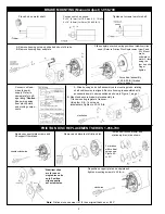
Position hub to X as shown:

X=.32” (8.1mm) for 1 & 2 disc (1.5 - 15 lb-ft)

X=.19” (4.8mm) for 3 disc (20 & 25 lb-ft)

Place hub on motor shaft.

Tighten set screws to motor shaft.

Connect coil lead-

wires to power 

supply. Refer to 

nameplate for volt-

age rating.*

Caution

Keep wiring away 

from pinch points 

and moving compo-

nents.

1

2

6

3

X

BRAKE MOUNTING (Manual Adjust) 1-056-700

*  Stabilizer clips 

are for use on  

single disc units 

only. Position 

clips opposite 

set screw holes.

Remove support plate screws and 

lift support from brake

Reposition support plate on endplate and 

tighten mounting screws to 55 lb-in.

Install new friction disc(s) and  

stationary disc(s) as shown.

Remove and discard old friction disc.

4

2

1

3

clockwise

For brakes 

with vertical 

sprngs see 

Figure 5A 

or 5C.

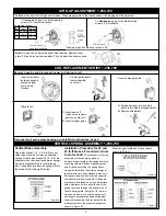
FRICTION DISC REPLACEMENT SERIES 1-056-700

2

Note

: Friction discs can wear to 1/2 their original thicknes, or .093”

A. Remove housing nuts and slide tie bolt out of brake. 

B. Remove housing from endplate.

4

* For vertical assembly  

of 20 & 25 lb-ft brakes  

refer to page 3.

Slide endplate over hub noting position of stabilizer clips, if 

used. (Refer to Friction Disc Replacement  view 3 and 

3A). Mount 

brake 

endplate to  

motor C-face 

using the 

four tie bolts. 


Finger 

tighten.

5

A. Slide housing and shaft assembly onto mounting studs, rotating  

shaft until keyway is aligned. Be sure housing is assembled with  

access windows in same position as shown in Figure 1, page 1.

B.  Mount and secure brake/motor assembly to  

C-face mounting register of reducer.  

Using four 3/8 - 16 nuts and  

lockwashers, tighten to 30-35 ft-lb.

clockwise

7

counter-clockwise

5

Summary of Contents for 1-056-700 Series

Page 1: ...k or a respirator while removing dust from the inside of a brake b Use a vacuum cleaner or a soft brush to remove dust from the brake When brushing avoid caus ing the dust to become airborne Collect the dust in a container such as a bag which can be sealed off 10 Caution While the brake is equipped with a manual release to allow manual shaft rotation the motor should not be run with the manual rel...

Page 2: ...1 3 clockwise For brakes with vertical sprngs see Figure 5A or 5C FRICTION DISC REPLACEMENT SERIES 1 056 700 2 Note Friction discs can wear to 1 2 their original thicknes or 093 A Remove housing nuts and slide tie bolt out of brake B Remove housing from endplate 4 For vertical assembly of 20 25 lb ft brakes refer to page 3 Slide endplate over hub noting position of stabilizer clips if used Refer t...

Page 3: ...stationary disc hole Springs are inserted from the side opposite the indent mark see Figure 2B Stationary disc should be placed on a clean flat surface with a clearance hole to allow the tip of the spring to extend through the bottom side of the sta tionary plate Using the 1 8 pin pro vided and a hammer drive the spring until the large coil diameter bottoms out against the disc Reassemble the disc...

Page 4: ...ndings of an Inverter motor or other voltage current limiting device Wire coil to dedicated power source with instantaneous coil rated voltage MISCELLANEOUS CAUSE MISCELLANEOUS CORRECTION Wrong or over tightened torque Replace with proper spring or refer to Installation section for proper spring height Excessive air gap Reset refer to Installation Section 4 EXCESSIVE WEAR OVERHEATING AIR GAP CAUSE...

Reviews: