background image

5 Operation

SPR-PRC-H

25 / 33

www.stauff.com

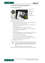
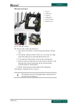
Fitting the workpiece

1

2

3

4

5

6

Fig. 16: Fitting the workpiece

1 Cap nut

2 Cutting ring

3 Tube end

4 Holding jaws

5 Counter retainer

6 Assembly stud

u

This is the way to fit the assembly stud:

1. Slip cap nut onto the tube. The thread must point towards the tube

end.

2. Then slip the cutting ring onto the tube end. In so doing, the cutting

edge of the cutting ring must point towards the tube end.

3. Press apart the holding devices of the counter retaining plate.

4. Insert the tube from above into the counter retainer and place on the

assembly stud. Cutting ring and cap nut are located between
assembly stud and counter retainer.

5. Slip the optional pressure sleeve between the holding jaws.

þ

Workpiece is prepared for the mounting.

Fit reinforcing sleeves for thin-walled tubes in keeping with the
STAUFF Product Catalogue!

Summary of Contents for SPR-PRC-H

Page 1: ...iginal instructions Mobile cutting ring pre assembly machine SPR PRC H To prevent injury and damage read this instruction manual carefully and attentively and retain it for future reference 6010016757...

Page 2: ...Ehrenfeld 4 58791 Werdohl Germany 49 2392 916 0 sales stauff com www stauff com More operating instructions in other languages can be found on www stauff com for download Mobile cutting ring pre asse...

Page 3: ...al protective equipment 12 3 Machine description 13 3 1 Machine overview 13 3 2 Function 13 3 3 Technical data 14 3 4 Nameplate 14 3 5 Tools and product 14 3 6 Assembling area 15 3 7 Display and opera...

Page 4: ...ne 4 33 www stauff com 6 1 Safety 29 6 2 Fault table 29 7 Maintenance 30 7 1 Safety 30 7 2 Inspection and maintenance work 30 7 3 Cleaning the machine 30 8 Decommissioning 31 8 1 Safety 31 8 2 Disposa...

Page 5: ...injury WARNING Failure to heed this warning notice may result in serious or fatal injury CAUTION Failure to heed this warning notice may result in slight or moderate injury ATTENTION Failure to heed t...

Page 6: ...dual action steps in the specified order Operating instructions are structured as follows and are identified by corresponding symbols u Objective of the operating instruction 1 Action step Effect of t...

Page 7: ...either to the steel steel or stainless steel stainless steel combinations Pre assemblies involving materials and material combinations at variance to the above need to be separately examined on the b...

Page 8: ...ical condition safely and aware of the hazards as intended Section 2 1 P 7 paying attention to this instruction manual with unchanged fully installed properly installed and fully functional safety dev...

Page 9: ...tripod Keep to the required break times 2 4 Tasks and duties of the operating company In addition to the instructions and information in this instruction manual the generally relevant legal and other...

Page 10: ...ng and cannot be accessed by the operator Push button with immediate stop function The hydraulic cylinder is activated only when the push button is pressed The drive is stopped when the button is rele...

Page 11: ...authorisations of the operating personnel Skilled jobs Certain qualifications are needed for a number of jobs Only those with the specified qualifications are allowed to perform the listed jobs Job Qu...

Page 12: ...mbly machine www stauff com 2 8 Personal protective equipment To limit hazards during work use the required personal protective equipment Symbol PPE Life phase Job Close fitting work clothing all all...

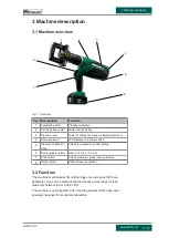
Page 13: ...isplays and power switch 5 Pressure adjustment wheel Setting the pressure cylinder setting 6 Rechargeable battery lithium ion 18 V 5 0 Ah 7 Push button Extend pressure cylinder under pressure 8 Return...

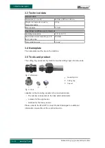
Page 14: ...009 79 dB A Total oscillation value 1 5 m s2 3 4 Nameplate The nameplate is at the top on the machine 3 5 Tools and product The cutting ring pre assembly machine mounts cutting rings onto tube ends Fi...

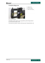
Page 15: ...1 2 3 Fig 4 Assembling area 1 Holding device 2 Pressure cylinder 3 Holding device spring The holding devices brace the cap nut against the cylinder being extended and can be pressed apart by hand At t...

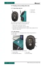
Page 16: ...s the following operating elements Power switch for switching on and off Push button for extending the pressure cylinder Return button for retracting the pressure cylinder also possible when the machi...

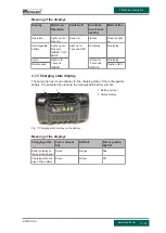
Page 17: ...for 1 second GREEN Light up for 10 seconds ORANGE No display Maintenance Flashes RED 3 7 3 Charging state display The hand grip has its own display for the charging state of the rechargeable battery I...

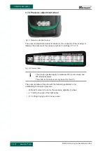
Page 18: ...e of the pressure cylinder in settings of 1 to 18 Fig 9 Pressure table The values specified apply to materials W3 carbon steel and W5 stainless steel The extra red values must only be set for the W5 T...

Page 19: ...0 Case with accessories 1 Mounting socket small 2 Assembly oil 3 Cutting ring pre as sembly machine 4 Replacement battery 5 Mounting socket to be separately ordered 6 Charger 3 8 2 Carrying strap To h...

Page 20: ...ring pre as sembly machine 2 Holding ring 3 Cylinder housing 4 Tripod 3 8 4 Table mount optional The machine can also be installed on a workbench using a table mount For this a clamping screw is faste...

Page 21: ...storage The machine is supplied with a case The machine should always be in the case when transporting or storing it This avoids any damage to the machine and hazards to people Information on dimensi...

Page 22: ...1 Safety WARNING Accessing during the pressing Shearing off and crushing of fingers Only operate the machine with the safety equipment installed and in working order Keep fingers away from the assembl...

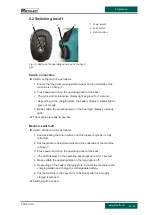
Page 23: ...ertain the operating lamp on the hand grip displays a steady light The machine is ready to operate Machine switch off u Switch off the machine as follows 1 Keep actuating the return button until the p...

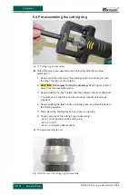
Page 24: ...r switch on the operating panel at the back 4 Keep extending the pressure cylinder with the pressure button until the clip in the groove can be reached 5 Pull out the clip 6 Position the assembly stud...

Page 25: ...ng ring onto the tube end In so doing the cutting edge of the cutting ring must point towards the tube end 3 Press apart the holding devices of the counter retaining plate 4 Insert the tube from above...

Page 26: ...g Keep fingers or items away from the assembling area 3 Keep actuating the push button until the setting pressure is obtained You will hear a slight click and the pressure cylinder extending is stoppe...

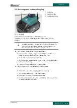
Page 27: ...is the way to charge the rechargeable battery 1 Ensure that the operation display does not light up and that as a result the machine is switched off Section 5 2 P 23 2 Connect the charger to the power...

Page 28: ...ation 28 33 Mobile cutting ring pre assembly machine www stauff com 1 2 3 Fig 20 Charger 1 Rechargeable battery 2 Charger 3 Charging pilot lamp More information on the charger is in its separate instr...

Page 29: ...flashes RED Defect with internal parts Contact the manufacturer Pressure cylinder does not extend itself Machine not switched on Switch on machine Flat rechargeable battery Charge the rechargeable bat...

Page 30: ...obs should be regularly carried out Before use examine the machine for any external damage Check LED displays Clean the machine after use 7 3 Cleaning the machine The machine and its components have t...

Page 31: ...g of the machine the operating company has to dispose of all used materials and components in keeping with the provisions in force in the country where machine is operated Particular care is required...

Page 32: ...rth in Low Voltage Directive 2014 35 EU Official Journal of the European Union L96 357 of 29 03 2014 have been complied with in accordance with Annex I No 1 5 1 of Machinery Directive 2006 42 EC The f...

Page 33: ...se 7 Intended use 7 L LED displays 16 O Operating company obligations 9 Operating elements 16 Operating panel 13 Operation End 23 Start 23 P Personal protective equipment 12 Power switch 16 Pressure a...

Reviews: