background image

8 / 12


9

11

10

Montar la matriz de crimpado

Fitting the crimping die

(fig. 9)

Las matrices de crimpado solo pueden 

introducirse con las asas abiertas� In-

troduzca las matrices por separado� La 

identificación láser de las matrices tiene 

que estar orientada hacia el operario al 

igual que la identificación de la crimpa-

dora� 

(ill. 9)

The crimping dies can be inserted only 

when the handles are open� Insert the 

dies separately� The laser identification 

of the dies needs to face towards the 

operator as well as the pliers identifica-

tion� 

 Atención


Al introducir las matrices, com-

pruebe que primero se introduce 

el yunque (matriz inferior) y solo 

después el punzón� 

 Attention


When inserting the dies make sure 

that the anvil (lower die) is inserted 

first, only then insert the punch� 


Cierre la crimpadora�


Coloque los tornillos en la posición 

correcta� No dañe las cabezas de los 

tornillos�


Close the pliers�


Place the screws in the correct po-

sition� Do not damage the screw 

heads�

(fig. 10)

Enrosque completamente los tornillos S 

(largo) y S1 (corto)�

(ill. 10)

Screw in screw S (long) and S1 (short) 

completely�

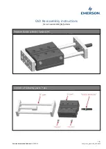
Montaje del posicionador

Locator assembly


Nota: 

Las imágenes describen el posicionador para los crimpados 

MC4-Evo 2� El montaje del posicionador para el MC4 es similar�


Note: 

The pictures describe the locator for MC4-Evo 2 crimps� The 

assembly of the locator for MC4 is comparable�

(fig. 11)

1. 

Fije el posicionador en el pasador guía�

2. 

Gire el posicionador (sostenido magnéticamente)�

3. 

Bloquee el posicionador�

(ill. 11)

1. 

Affix locator onto the guide pin�

2. 

Rotate the locator (held magnetically)�

3. 

Lock the locator�

1

2

3

Summary of Contents for 32.6020-60100

Page 1: ...a PV CZM Crimping tool PV CZM Contenido Instrucciones de seguridad 2 Volumen de suministro 3 Piezas individuales 6 Cambiar la matriz de crimpado 7 Posicionador 8 Crimpado 9 Content Safety Instructions 2 Scope of delivery 3 Individual parts 6 Exchanging the crimping die 7 Locator assembly 8 Crimping 9 Sección del conductor Conductor cross sections 2 5 mm 4 mm 6 mm Sección del conductor Conductor cr...

Page 2: ...sult in life threatening injuries due to electric shock elec tric arcs fire or failure of the system Follow the entire instruction manual Use the product only according to this instruction manual and the technical data The digital instruction manual and the technical data are available at www staubli com electrical Uso previsto Las herramientas manuales actuales están preparadas para ofrecer un ex...

Page 3: ...ors Crimpadoras Crimping pliers Posicionadores Locators Matriz de crimpado Crimping die 2 5 mm 4 mm 6 mm PV CZM 61100 32 6020 61100 32 6082 32 6084 Conectores MC4 MC4 connectors Conectores MC4 EVO 2 MC4 EVO 2 connectors 32 6021 61100 4 mm 6 mm 10 mm PV CZM 60100 32 6020 60100 32 6081 Conectores MC4 EVO 2 MC4 EVO 2 connectors Conectores MC4 MC4 connectors 32 6083 32 6021 60100 ...

Page 4: ... 6021 60100 PV ES CZM 61100 32 6021 61100 4 mm 6 mm 10 mm PV LOC MC4 32 6081 2 5 mm 4 mm 6 mm PV LOC MC4 32 6082 4 mm 6 mm 10 mm PV LOC MC4 EVO 2 32 6083 2 5 mm 4 mm 6 mm PV LOC MC4 EVO 2 32 6084 PV KBT4 2 5 UR PV KST4 2 5 UR 2 5 mm 14 AWG PV KBT4 6 UR PV KST4 6 UR 4 mm 12 AWG 6 mm 10 AWG PV KBT4 10 PV KST4 10 10 mm PV KST4 EVO 2 2 5 UR PV KBT4 EVO 2 2 5 UR 2 5 mm 14 AWG PV KST4 EVO 2 6 UR PV KBT4...

Page 5: ...ong with the available inserts listed in the above table do not provide any feasible crimping for barrel crimps Barrel crimps will become unuse able Nota Las crimpadoras no están diseñadas para ser utilizadas junto con los terminales de crimpado PV KST4 5 PV KBT4 5 PV KST4 8 PV KBT4 8 Ver tabla en página 4 Note The crimping pliers are not designed for to be used along with crimping terminals PV KS...

Page 6: ...PV LOC MC4 EVO 2 Order No 32 6083 Atención Los posicionadores con cuerpo metálico negro solo deben utilizar se para los terminales de crimpado MC4 Los posicionadores con cuerpo metálico gris solo deben utilizarse para los terminales de crimpado MC4 EVO 2 Attention The locators with black metal body must be used only for MC4 crimp terminals The locators with grey metal body must be used only for MC...

Page 7: ...amente el torni llo S largo y S1 corto con una llave Allen de 2 5 mm no incluida en la entrega Abra la crimpadora ill 6 Completely unscrew screw S long and S1 short completely using an Allen key 2 5 mm not included in delivery Open the pliers fig 7 Retire la matriz de crimpado superior ill 7 Remove the upper crimping die fig 8 Retire la matriz de crimpado inferior ill 8 Remove the lower crimping d...

Page 8: ...sure that the anvil lower die is inserted first only then insert the punch Cierre la crimpadora Coloque los tornillos en la posición correcta No dañe las cabezas de los tornillos Close the pliers Place the screws in the correct po sition Do not damage the screw heads fig 10 Enrosque completamente los tornillos S largo y S1 corto ill 10 Screw in screw S long and S1 short completely Montaje del posi...

Page 9: ...until the crimping flaps are properly located within the crimping die fig 14 Inserte el extremo pelado del cable hasta que los cables trenzados se topen con el posicionador Cierre por completo las crimpadoras ill 14 Insert the stripped cable end until the cable strands come up against the clamp Completely close the crimping pliers Nota Respete la longitud de pelado del proveedor de cables fotovolt...

Page 10: ...impado para los cables PV de Stäubli Flex Sol Evo TX y Flex Sol Evo DX Verify crimp height Typical values for the crimp height for Stäubli PV cable Flex Sol Evo TX and Flex Sol Evo DX are listed below Altura del crimpado Crimp height Ancho del crimpado Crimp width WZ 1 61100 MC4 Evo 2 Sección del conductor Conductor cross section mm Codificación Coding Sección del conductor Conductor cross section...

Page 11: ...tact type N º de pedido Order No 4 B2 12 2 15 4 20 PV SP4 EVO 2 6 PV BP4 EVO 2 6 32 0521P 32 0121P 6 C2 10 2 4 4 28 PV SP4 EVO 2 6 PV BP4 EVO 2 6 32 0521P 32 0121P 10 D2 8 3 02 5 65 PV SP4 EVO 2 10 PV BP4 EVO 2 10 32 0522P 32 0122P MC4 Sección del conductor Conductor cross section mm Codificación Coding Sección del conductor Conductor cross section AWG Altura del crimpado Crimp height 0 05 mm Anch...

Page 12: ...4 05 2022 Index a Marketing Communications Sujeto a modificaciones Subject to alterations Crimpado correcto Good crimp Crimpado incorrecto Las partes estampadas se doblan incorrectamente Bad crimps Stamped parts bent wrongly El material fluye hacia fuera Material flow outwards Aletas de crimpado abiertas Open crimp wings Hilos no incluidos Not included strands Inspección visual de los crimpados re...

Reviews: