background image

Status 

Pro

–  

T250 Instruction manual

11

OPERATION

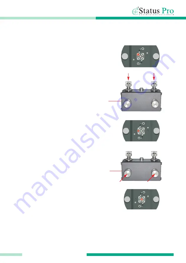
a. Laser point hits the top left hand

corner (X - / Y -).

Screw in both the Y-screws equally 
in a clockwise manner. The beam is 
moved in a parallelly downwards. 

b. Now the laser beam is corrected in 

the height, but still hits the sensor left
of the centre. 

Screw in both the X-screws equally 
in a clockwise manner. The beam is 
moved parallelly sideways.

c. Now the laser beam is corrected 

vertically and horizontally.

9)

Move the sensor as far as possible from the laser again, and check the position of the 

laser point on the sensor, if necessary, repeat steps 6-8.

When using the ProLine Software, measurement points can be „zeroed“ at will to obtain
the straightness of the guide in respect to these two points.

8)

Adjust the laser beam parallelly to the centre of the sensor using the (X1 + X2 /
Y1 + Y2) screws (equally):

Summary of Contents for T250

Page 1: ...T250 Laser transmitter Instruction manual Another fine solution by ...

Page 2: ...ser Manuals can be amended when improvements or changes to the prouct range have been carried out Use the link below to make sure you have the most up to date version of your User Manual www statuspro com machine_geometry documents Contents 1 SAFETY INSTRUCTIONS 3 1 1 Class of laser 3 1 2 Standards 4 1 3 Instrument care 4 1 4 Maintenance 4 1 5 Calibration 5 1 6 Liability Exclusion 5 2 GETTING STAR...

Page 3: ...aser beam Do not point the laser beam at other people Observe the local safety guidelines on Site and if in doubt consult the Site safety Engineer Do not use the equipmentin damp or moist locations Ensure shading of the equipment against direct sunlight or heat sources Fluids or rain as well as extreme temperature conditions may damage the equipment Note Do not violently shake the Laser or other s...

Page 4: ...cloth Do not use paper towels to clean glass surfaces as they could scratch Avoid contact with grease oil or oil based solutions when handling the equipment 1 4 Maintenance The mechanical components of your equipment are prone to natural wear and tear If the Instrument appears to have a technical defect contact the Manufacturer Das Gerät nicht eigenständig öffnen Attempted repairs through unauthor...

Page 5: ... date of the next service check for your equipment is stamped on the Status Pro calibration sticker To ensure trouble free processing of the service and calibration checks simply use the form you will find using the following link www statuspro com machine_geometry service_support calibration_repair 1 6 Liability Exclusion The Status Pro GmbH does not accept responsibility for damage incurred thro...

Page 6: ...5 and an Adapter II 832050 enabling mounting of the T250 Laser when using a tripod or when using the Borealign Kit SP BOREALIGN 2 1 Power supply To operate the T250 connect the power supply cable to the mains and to the socket on the T250 housing Ensure that the red markings on the plug and the socket are correctly aligned This ensures correct polarity II Adapter III Power supply cable I Laser tra...

Page 7: ...vered the T250 will have four screws on the front and the back facing The cylindrical face of the adapter has a 5 8 thread for use with a tripod fitting To enable mounting on a vertical surface or for use with the Borealign kit the Adapter II can be fitted to the front or the rear facing again using the supplied screws The 5 8 thread is continuous so the laser beam has sight through the Adapter II...

Page 8: ...nd a locking nut for the coarse adjustment screw 3 To roughly adjust the laser beam loosen the locking nut align the laser beam with the coarse screw 2 and the tighten up the locking nut again Fine adjustment is carried out with locking nut tightened up When the T250 is in the horizontal position see below the two screws on the upper side Y1 Y2 are used to align the laser beam vertically The two s...

Page 9: ...gle as well as the parallel shift in both the vertical and the horizontal plane Example 1 If the Y1 screw is moved downwards screwed in then the angle of the laser beam will also slope downwards 2 If both Y1 and Y2 are moved downwards screwed in then the laser laser beam will move parallelly downwards parallel shift The adjustments in the horizontal plane X1 X2 are carried out in exactly the same ...

Page 10: ...to carry out the measurement of a Linear guide 1 Mount the T250 on a tripod or directly on the machine to be measured 2 Connect the T250 to an appropriate power supply 3 Position the sensor on the guide as close as possible to the T250 4 Carry out a rough adjustment of the T250 Laser itself so the laser beam meets the centre of the detector 5 Move the detector as far away as possible from the T250...

Page 11: ... equally in a clockwise manner The beam is moved parallelly sideways c Now the laser beam is corrected vertically and horizontally 9 Move the sensor as far as possible from the laser again and check the position of the laser point on the sensor if necessary repeat steps 6 8 When using the ProLine Software measurement points can be zeroed at will to obtain the straightness of the guide in respect t...

Page 12: ...ser range 100 m Temperature range 0 50 C Socket type Lemo Housing Aluminium anodisied Protection class IP 54 Dimensions 120 x 90 x 90 Weight 950g Attachment possibilities Four M5 threads on the Front Back and Underside 8 Lemo connector lock ring pre adjust ment pre adjust ment vernier adjustment ø 20 48 48 4x M5 x 20 48 48 85 90 60 85 90 60 30 30 80 120 40 5 ...

Page 13: ...ly with Lemo plug for the T250 Laser The supply is delivered with various adapters for global use and is CE certified Bore Measurement kit SP BOREALIGN Package for measuring boreways on marine engines or rudder tubes etc Measurements on Bore diameters from 60 mm up to several metres is possible Fitting of the laser and sensor in the bores as well as on the facing is possible The sensor attachment ...

Page 14: ...nd rubber housing protection as well as a screen protector Fixed internal cells as well as a hot swap external recharge able battery pack Suitable for field use Communication with Status Pro sensors using USB and Bluetooth Tripods for the Laser or sensors FIX STATIV 01 P FIX STATIV 04 P Tripod 01 P Adjustment range 545 935 mm Weight 5 5 kg Tripod 1 5 P Adjustment range 760 1700 mm Weight 12 kg Tri...

Page 15: ...of a laser beam reference together with tradition industrial measurement techniques has made it possible to build tools which simplify these alignment procedures Status Pro develops and manufactures laser alignment equipment and we are committed to this process Most of our customers are machine builders assembly and quality con trol people Typically our customers require a complete solution packag...

Page 16: ...esign D 44229 Dortmund Copyright 2010 Status Pro Maschinenmesstechnik GmbH This brochure or parts thereof may not be copied or reproduced in any other way without prior approval by Status Pro GmbH Technical correctness and completeness remain reserved and may be subject to changes without prior information Information about mistakes this brochure may contain will be welcome at any time Distributor...

Reviews: