background image

26

8.  If the Flame Sensor does not detect a strong enough flame, the 

Ignition Control shuts off the Gas Valve and allows the blower to 

purge the unit for 30 seconds.  At that time, the Ignition Control 

restarts with step 6. It will try and ignite the main burners 2 more 

times.  If the unit does not light, the Ignition Control will wait 15 

minutes and then restart at step 6. This cycle will continue until the 

unit lights or the power is shutoff to the unit.

9.  If the Flame Sensor detects a strong flame, the Ignition Control 

will  energize  the  main  gas  valve  output,  which  will  cause  the 

blower to run at a pre-determined high speed until call-for-heat 

is removed.

10. Once the unit is satisfied, the Thermostat will shut off the blower, 

Gas  Valve  and  Ignition  Control  and  the  unit  will  be  in  standby 

mode until another call for heat is initiated by the thermostat.

See the flow chart on page 27 for more detailed information.

seQuenCe of operation

The following information will describe the Sequence of Operation 

for this water heater.
1.  Switch power on to unit.
2.  Thermostat calls for heat.
3.  UGb send PWM  signal to blower to start the blower at high pre-

purge speed.

4.  The blower pressure switch is closed, 24VAC power is applied to 

the Ignition Control Module.

5.  20  seconds  later  blower  starts  to  slow  down  to  a  slow  ignition 

speed preparing for ignition process.

6.  30 seconds after being energized, the Ignition Control provides 

power to the Spark Igniter and opens the Gas Valve.

7.  Ignition Control maintains spark for up to 4 seconds and monitors 

Flame Sensor to determine if burner is lit.

lighting & operating laBel

S

N

O

I

T

C

U

R

T

S

N

G

N

I

T

A

R

E

P

O

G

N

IT

A

R

E

P

O


E

R

O

F

E

B


D

A

E

R


Y

T

E

F

A

S


R

U

O

Y


R

O

F

1.

2.

STOP!  Read the safety information

above on this label.

Set the ON/OFF switch on the control box to

the “OFF” position.

6. Turn on all electrical power to the appliance.

7. Set the ON/OFF switch on the control box to

the “ON” position.

8. Set the thermostat to the desired setting.

9. If the appliance will not operate, follow the

instructions “TO TURN OFF GAS TO

APPLIANCE” and call your technician or gas

supplier.

Wait five (5) minutes          to clear out any gas.

If you then smell gas,         STOP!  Follow “B”

in the safety information above on this label.  If

you don’t smell gas, go to the next step.

3. Set the thermostat to the lowest setting.
4. This appliance is equipped with a device which

automatically lights the burner.

DO NOT TRY TO LIGHT THE BUNER BY HAND.

5.

CAUTION: Hotter water increases the risk

of scald injury.  Consult the instruction

manual before changing temperature.

WARNING: TURN OFF ALL ELECTRIC

POWER BEFORE SERVICING.

FLAMMABLE

WARNING: 

If you do not follow these instructions exactly, a fire or

explosion may result causing property damage, personal injury

or loss of life. 

BEFORE OPERATING: ENTIRE SYSTEM MUST BE FILLED WITH WATER AND AIR PURGED FROM ALL LINES.

A.

B.

This appliance does not have a pilot.  It is equipped with

an ignition device which automatically lights the burner.


Do not try to light the burner by hand. 

C. Use only your hand to push the control buttons. Never use

tools.  If the control buttons will not push in, don’t try to

repair them, call a qualified service technician.  Force or

attempted repair may result in a fire or explosion.

D. Do not use this appliance if any part has been under water.

Immediately contact a qualified installer or service agency

to replace a flooded water heater.  Do not attempt to repair

the unit.  It must be replaced!

BEFORE OPERATING smell all aroung the area for gas.

Be sure to smell next to the floor because some gas is

heavier than air and will settle on the floor.

WHAT TO DO IF YOU SMELL GAS

Do not try to light any appliance.

Immediately call your gas supplier from a neighbor's

phone.  Follow the gas suppliers instructions.

If you cannot reach your gas supplier, call the fire

department.

Do not touch any electric switch;

do not use any phone in your building.

2. Set the ON/OFF switch on the control box to

the “OFF” position.

1. Set the thermostat to the lowest setting.

3. Turn off all electrical power to the appliance

if service is to be performed.

TO TURN OFF GAS TO APPLIANCE

ON

OFF

figure 23.

Summary of Contents for SBL81120NE

Page 1: ...and liquids in the vicinity of this or any other appliance WHAT TO DO IF YOU SMELL GAS Do not try to light any appliance Do not touch any electrical switch do not use any phone in your building Immed...

Page 2: ...ion 32 Start Up Conditions 32 Operational Conditions 32 Troubleshooting 33 Water Piping Diagrams 34 Notes 50 Limited Warranty 51 Table Of Contents Safe Installation Use and Service 3 APPROVALS 3 Gener...

Page 3: ...of California to cause cancer birth defects or other reproductive harm and requires businesses to warn of potential exposure to such substances Warning This product contains a chemical known to the St...

Page 4: ...ion Contact a qualified installer or service agency for installation and service Excessive gas pressure to gas valve can cause serious injury or death Do not use water heater with any gas other than t...

Page 5: ...ter system If hydrogen is present there will probably be an unusual sound such as air escaping through the pipe as the water begins to flow There should be no smoking or open flame near the faucet at...

Page 6: ...his manual first and then the entire manual carefully If you don t follow the safety rules the water heater will not operate properly It could cause DEATH SERIOUS BODILY INJURY AND OR PROPERTY DAMAGE...

Page 7: ...water heater cannot be restarted unless the water temperature is reduced to approximately 120 F 49 C The high limit reset button on the front of the control then needs to be depressed Continued manual...

Page 8: ...61 67 70 72 78 SBL81120NE 120 81 82 GPH 331 298 239 221 199 170 166 149 133 119 110 108 99 95 92 85 35 307 LPH 1254 1129 903 836 752 645 627 564 502 451 418 410 376 358 347 322 SBL81154NE 154 81 82 GP...

Page 9: ...eiling must be a continuous run no joints and retain 6 15 2 cm clearance unless an approved reducing thimble is used A service clearance of at least 24 61 cm should be maintained from serviceable part...

Page 10: ...n labels from the manufacturer for placement on the blanket directly over the existing labels DO inspect the insulation blanket frequently to make certain it does not sag thereby obstructing combustio...

Page 11: ...MP WIRING DIAGRAM STORAGE TANK OR BUILDING RECIRCULATION FIELD SUPPLIED TEMPERATURE CONTROL INSTALLED IN THE STORAGE TANK OR CIRCULATING LOOP RETURN LINE CIRC PUMP MOTOR L1 HOT L2 NEUTRAL 120 VAC POWE...

Page 12: ...tic pressure and with all gas burning equipment running at maximum rate dynamic pressure The gas supply pressure must be stable within 1 5 W C 0 37 kPa from static to dynamic pressure to provide good...

Page 13: ...ge 20 and Water Piping Diagrams on page 34 Temperature Pressure Relief Valve Explosion Hazard Temperature Pressure Relief Valve must comply with ANSI Z21 22 CSA 4 4 and ASME code Properly sized temper...

Page 14: ...not intended for the constant relief of thermal expansion A properly sized thermal expansion tank must be installed on all closed systems to control thermal expansion see Closed Water Systems and Ther...

Page 15: ...tand instruction manual For safe operation an adequate supply of fresh uncontaminated air for combustion and ventilation must be provided An insufficient supply of air can cause recirculation of combu...

Page 16: ...Figure 15 Alternatively a single permanent opening commencing within 12 inches 300 mm of the top of the enclosure shall be provided See Figure 14 The water heater shall have clearances of at least 1 i...

Page 17: ...aggregate input rating of all appliances installed in the enclosure Each opening shall not be less than 100 square inches 645 cm2 Outdoor Air Through Two Vertical Ducts The illustrations shown in thi...

Page 18: ...nector size 6 inches 6 8 10 15 20 30 50 100 Input Btu hr Rise Vent Connector Diameter Inches 154 000 1 ft 6 6 6 6 6 6 6 6 154 000 2 ft 6 6 6 6 6 6 6 6 154 000 3 ft 6 6 6 6 6 6 6 6 Number of 154 Heater...

Page 19: ...15 20 30 50 100 Input Btu hr Rise Vent Connector Diameter Inches 250 000 1 ft 8 8 7 7 7 6 6 6 250 000 2 ft 7 7 7 7 6 6 6 6 250 000 3 ft 7 7 7 7 6 6 6 6 Number of 250 Heaters Combined Input in Thousand...

Page 20: ...installation of the water piping begins 1 Water Temperature Control and Mixing Valves on page 12 2 Dishwashing Machines on page 13 3 Temperature Pressure Relief Valve on page 13 4 Closed Systems and T...

Page 21: ...ing heat to this fitting Do not allow pipe dope to contact the plastic tube during installation Tube Inlet Installation Figure 19 TEMPERATURE SETTING SHOULD NOT EXCEED SAFE USE TEMPERATURE AT FIXTURES...

Page 22: ...n to properly wire the hot and neutral connections IF ANY OF THE ORIGINAL WIRE AS SUPPLIED MUST BE REPLACED USE ONLY 18 AWG 105 C 600V UL AWM STYLE 1015 WIRE EXCEPT GAS VALVE CABLE WHICH MUST USE 2 CO...

Page 23: ...attaching the gas line be sure that all gas pipe is clean on the inside To trap any dirt or foreign material in the gas supply line a sediment trap must be incorporated in the piping see Figure 21 Th...

Page 24: ...s away from faucets after extended periods of non use 1 Close the Main Gas Shutoff Valve see Figure 21 on page 23 2 Purge all air from the supply gas line up to the water heater s Main Gas Shutoff Val...

Page 25: ...gas regulator as necessary Adjust the supply gas regulator s per the regulator manufacturer s instructions to achieve the required static and dynamic supply gas pressure Multiple Water Heater Installa...

Page 26: ...the desired setting 9 If the appliance will not operate follow the instructions TO TURN OFF GAS TO APPLIANCE and call your technician or gas supplier Wait five 5 minutes to clear out any gas If you th...

Page 27: ...to determine if Burner is lit Does Burner light Ignition Control changes Blower from low speed to high speed after 5 seconds Ignition Control monitors flame signal Thermostat is satisfied Blower off B...

Page 28: ...y thermal expansion in a closed system See Closed Water Systems and Thermal Expansion on page 13 The Temperature Pressure Relief Valve is not intended for the constant relief of thermal expansion Temp...

Page 29: ...hismanual 11 Turn on the electrical supply to place the water heater back in operation 12 Turn on the gas supply to the water heater at the Main Gas Shutoff Valve 13 Allow the water heater to complete...

Page 30: ...ut opening and scrape out any loose deposits of scale or sediment This is an economical way to avoid unnecessary usage of the deliming solution Repeat the opening and closing of the cold water inlet v...

Page 31: ...t fitting into the drain valve opening of heater after applying Teflon tape or paste to threads Tighten firmly by hand and use wrench or adjustable pliers to check for secure connection Do not over ti...

Page 32: ...be restarted unless the water temperature is reduced to approximately 120 F 49 C The high limit reset button on the front of the thermostat then needs to be depressed See Figure 2 for the location of...

Page 33: ...blockage and or flue gas exhaust blockage Water temperature too hot Thermostat set too high Set thermostat to a lower setting Rumbling Sediment accumulation on bottom of tank Drain a quantity of water...

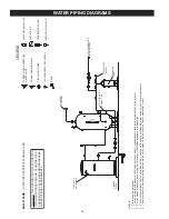
Page 34: ...should be set 5 degrees F higher than the Tank Temperature Control MULTI FLUE 1 UNIT WITH VERTICAL STORAGE TANK LEGEND TEMPERATURE PRESSURE RELIEF VALVE PRESSURE RELIEF VALVE CIRCULATING PUMP TANK TE...

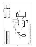
Page 35: ...ostat should be set 5 degrees F higher than the Tank Temperature Control MULTI FLUE 1 UNIT WITH HORIZONTAL STORAGE TANK LEGEND TEMPERATURE PRESSURE RELIEF VALVE PRESSURE RELIEF VALVE CIRCULATING PUMP...

Page 36: ...and the storage tank s MULTI FLUE 1 UNIT WITH MIXING VALVE TWO TEMPERATURE LEGEND TEMPERATURE PRESSURE RELIEF VALVE PRESSURE RELIEF VALVE CIRCULATING PUMP TANK TEMPERATURE CONTROL DRAIN FULL PORT BAL...

Page 37: ...mp between the water heater s and the storage tank s MULTI FLUE 2 UNITS LEGEND TEMPERATURE PRESSURE RELIEF VALVE PRESSURE RELIEF VALVE CIRCULATING PUMP TANK TEMPERATURE CONTROL DRAIN FULL PORT BALL VA...

Page 38: ...tat should be set 5 degrees F higher than the Tank Temperature Control MULTI FLUE 2 UNITS WITH VERTICAL STORAGE TANK LEGEND TEMPERATURE PRESSURE RELIEF VALVE PRESSURE RELIEF VALVE CIRCULATING PUMP TAN...

Page 39: ...tat should be set 5 degrees F higher than the Tank Temperature Control MULTI FLUE 2 UNITS WITH VERTICAL STORAGE TANK LEGEND TEMPERATURE PRESSURE RELIEF VALVE PRESSURE RELIEF VALVE CIRCULATING PUMP TAN...

Page 40: ...t should be set 5 degrees F higher than the Tank Temperature Control MULTI FLUE 2 UNITS WITH HORIZONTAL STORAGE TANK LEGEND TEMPERATURE PRESSURE RELIEF VALVE PRESSURE RELIEF VALVE CIRCULATING PUMP TAN...

Page 41: ...EMPERATURE PRESSURE RELIEF VALVE PRESSURE RELIEF VALVE CIRCULATING PUMP TANK TEMPERATURE CONTROL DRAIN FULL PORT BALL VALVE TEMPERATURE GAGE WATER FLOW SWITCH CHECK VALVE WARNING THIS DRAWING SHOWS SU...

Page 42: ...VALVE CIRCULATING PUMP TANK TEMPERATURE CONTROL DRAIN FULL PORT BALL VALVE TEMPERATURE GAGE WATER FLOW SWITCH CHECK VALVE WARNING THIS DRAWING SHOWS SUGGESTED PIPING CONFIGURATION AND OTHER DEVICES C...

Page 43: ...LEGEND TEMPERATURE PRESSURE RELIEF VALVE PRESSURE RELIEF VALVE CIRCULATING PUMP TANK TEMPERATURE CONTROL DRAIN FULL PORT BALL VALVE TEMPERATURE GAGE WATER FLOW SWITCH CHECK VALVE WARNING THIS DRAWING...

Page 44: ...an the Tank Temperature Control MULTI FLUE 3 UNITS WITH VERTICAL STORAGE TANK LEGEND TEMPERATURE PRESSURE RELIEF VALVE PRESSURE RELIEF VALVE CIRCULATING PUMP TANK TEMPERATURE CONTROL DRAIN FULL PORT B...

Page 45: ...than the Tank Temperature Control MULTI FLUE 3 UNITS WITH HORIZONTAL STORAGE TANK LEGEND TEMPERATURE PRESSURE RELIEF VALVE PRESSURE RELIEF VALVE CIRCULATING PUMP TANK TEMPERATURE CONTROL DRAIN FULL PO...

Page 46: ...RE PRESSURE RELIEF VALVE PRESSURE RELIEF VALVE CIRCULATING PUMP TANK TEMPERATURE CONTROL DRAIN FULL PORT BALL VALVE TEMPERATURE GAGE WATER FLOW SWITCH CHECK VALVE WARNING THIS DRAWING SHOWS SUGGESTED...

Page 47: ...perature Control MULTI FLUE 4 UNITS WITH VERTICAL STORAGE TANK LEGEND TEMPERATURE PRESSURE RELIEF VALVE PRESSURE RELIEF VALVE CIRCULATING PUMP TANK TEMPERATURE CONTROL DRAIN FULL PORT BALL VALVE TEMPE...

Page 48: ...emperature Control MULTI FLUE 4 UNITS WITH HORIZONTAL STORAGE TANK LEGEND TEMPERATURE PRESSURE RELIEF VALVE PRESSURE RELIEF VALVE CIRCULATING PUMP TANK TEMPERATURE CONTROL DRAIN FULL PORT BALL VALVE T...

Page 49: ...49 Model Dimension A SBL 120 154 68 SBL 180 199 250 A 76...

Page 50: ...50 Notes...

Page 51: ...is also installed at the heater s and operational at all times The relief valve installed on the heater is not an acceptable method 4 SERVICE AND REPAIR EXPENSES Under the limited warranty the warrant...

Page 52: ...500 Tennessee Waltz Parkway Ashland City TN 37015 Tech Support 800 365 0024 Parts 800 821 2017 www statewaterheaters com Copyright 2012 State Water Heaters All rights reserved...

Reviews: