background image

Instruction manual

26

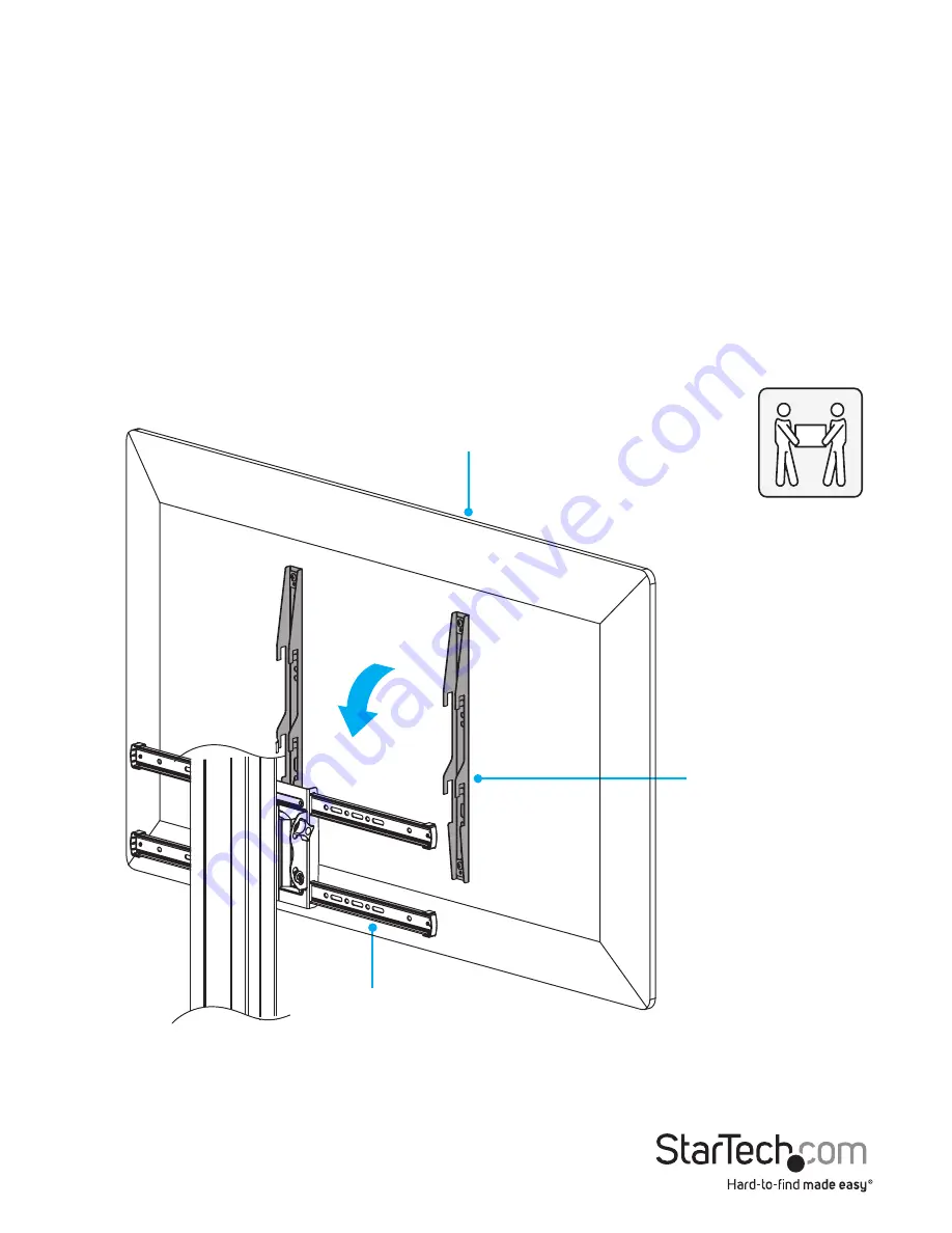
Attach the TV to the column

Warning! Attaching the TV requires multiple people. Do not attempt to complete this 

task by yourself.
Warning! Make sure that you move the support plate to the lowest position on the 

column before you attach the TV. For more information, see the “Move the support 

plate to the lowest position” section. 

1.  If you haven’t done so already, press the pedal locks down on each of the casters to 

prevent the legs from moving as you attach the TV to the column.

2.  With a person holding each side of the TV, carefully lift up the TV and hook the 

adapter brackets over the crossbars. (

figure 16

)

figure 16

Adapter bracket

Crossbar

Top of TV

Summary of Contents for STNDMTV70

Page 1: ...MTV70 FR Guide de l utilisateur fr startech com DE Bedienungsanleitung de startech com ES Guía del usuario es startech com NL Gebruiksaanwijzing nl startech com PT Guia do usuário pt startech com IT Guida per l uso it startech com STNDMTV70 Mobile Media Center for Flat Screen TV One Touch Height Adjustment actual product may vary from photos ...

Page 2: ...rTech com Where they occur these references are for illustrative purposes only and do not represent an endorsement of a product or service by StarTech com or an endorsement of the product s to which this manual applies by the third party company in question Regardless of any direct acknowledgement elsewhere in the body of this document StarTech com hereby acknowledges that all trademarks registere...

Page 3: ...en över kablar eller ojämna ytor Innan du börjar flytta på vagnen se till att hjulen är upplåsta Dichiarazioni di avvertenza Assicurarsi di Assemblare il prodotto secondo le istruzioni Leggere l intero manuale e assicurarsi di aver compreso tutte le istruzioni prima di iniziare ad assemblare e a utilizzare questo prodotto Non superare la capacità di carico del prodotto Il sovraccarico del prodotto...

Page 4: ... o peso da carga montada precisa de seguir os passos no manual para reajustar este produto Advertencias de uso Asegúrese de ensamblar este producto según las instrucciones Lea todo el manual y asegúrese de haber comprendido bien las instrucciones antes de proceder con el ensamblaje y el uso de este producto Asegúrese de no exceder la capacidad de peso de este producto La sobrecarga de este product...

Page 5: ... to the base 13 Assemble the TV mount 16 Attach the support plate to the column 17 Move the support plate to the lowest position 19 Attach the adapter brackets to a flush mounting surface 21 Attach the adapter brackets to a recessed mounting surface 23 Attach the TV to the column 26 Counterbalance the weight of the TV 29 Attach the plastic cover 30 Attach the cable clips 32 Install the multimedia ...

Page 6: ...V70 39 Change the orientation of the TV 39 Adjust the angle of the TV 40 Adjust the height of the multimedia shelf 41 Adjust the height of the camera shelf 42 Lock the vertical position of the TV 43 Technical support 44 Warranty information 44 ...

Page 7: ... Product dimensions min 200 mm to max 600 mm 723 mm 230 mm 150 mm 285 mm max 2140 mm min 1110 mm to max 1510 mm 828 mm 700 m m 430 mm 335 m m 290 mm 145 mm min 200 mm to max 404 mm 440 mm Support plate rotation 0 to 90 TV tilt 5 to 12 ...

Page 8: ...Instruction manual 2 Product diagram Camera shelf Adapter bracket Crossbar Support plate Column Multimedia shelf Pedal lock Right leg Left leg Plastic cover Base Connecting plate Caster ...

Page 9: ...A mounting hole pattern on the TV mount 200x200 300x300 400x200 400x400 600x400 Weight capacity of TV mount 40 kg 88 lb Lift capacity of TV mount 8 to 25 kg 18 to 55 lb Note If you exceed the lift capacity you will require additional manual force to raise the TV Weight capacity of multimedia shelf 5 kg 11 lb Weight capacity of camera shelf 5 kg 11 lb Screen size 32 to 75 ...

Page 10: ...Instruction manual 4 Package contents Base Qty One Left leg Qty One Right leg Qty One Left base cover Qty One Right base cover Qty One Left support bracket Qty One 2 1 3 4 6 5 ...

Page 11: ...Instruction manual 5 Right support bracket Qty One Column cover Qty One Column Qty One Multimedia shelf Qty One Camera shelf Qty One Connecting plate Qty One 8 7 9 10 11 12 ...

Page 12: ...Instruction manual 6 Plastic cover Qty One Cable clips Qty Three Adapter brackets Qty Two Crossbars Qty Two End caps Qty Four Support plate Qty One 13 14 15 16 17 18 ...

Page 13: ...Instruction manual 7 Wrench Qty One Hook and loop ties Qty Two M6x16 mm screws Qty Four M6x25 mm screws Qty Two Support plate nuts Qty Two Countersunk screws Qty Three 19 20 21 24 22 23 ...

Page 14: ...Instruction manual 8 M4x6 mm screws Qty Two M6x8 mm screws Qty Six M6x14 mm screws Qty Ten M8x25 mm screws Qty Four Washers Qty Four Shelf spacers Qty Four 26 29 25 28 27 30 ...

Page 15: ...Instruction manual 9 Hex key Qty One Caster wrench Qty One M5x14 mm screws Qty Four M6x14 mm screws Qty Four M6x30 mm screws Qty Four M8x30 mm screws Qty Four 31 32 33 34 35 36 ...

Page 16: ...rge spacers Qty Eight Instruction manual Qty One Requirements A TV that is compatible with one of the VESA mounting hole patterns STNDMTV70 supports A Phillips type screwdriver Requirements are subject to change For the latest requirements please visit www StarTech com STNDMTV70 37 38 39 40 41 ...

Page 17: ...ut assistance Assemble the base 1 Insert the base into the left leg aligning the holes in the base with the holes in the left leg 2 Insert two M6x16 mm screws through the left leg and into the base 3 Use the hex key to tighten the M6x16 mm screws 4 Repeat steps 1 to 3 to attach the right leg figure 1 figure 1 Right leg Left leg Base M6x16 mm screw Hex key ...

Page 18: ...s so that the casters are balanced and the assembly doesn t rock 1 Use the caster wrench to loosen the nuts above the casters 2 Rotate the casters counterclockwise or clockwise to raise or lower the casters to the desired height 3 Use the caster wrench to tighten the nuts figure 2 figure 2 Caster Nut Wrench ...

Page 19: ... Snap the column cover onto the top of the column figure 3 figure 3 Column cover Column 2 Press the pedal locks down on each of the casters to lock them in place and prevent the legs from moving as you attach the column figure 4 figure 4 Caster Pedal lock ...

Page 20: ...f the column with the holes in the base 4 While another person holds the column upright insert the four M8x25 mm screws through the base and into the column 5 Use the hex key to tighten the M8x25 mm screws figure 5 figure 5 Column M8x25 mm screw Hex key Base ...

Page 21: ...Instruction manual 15 6 Snap the left base cover and the right base cover onto the base and legs figure 6 figure 6 Base Right base cover Left base cover ...

Page 22: ...so that they are centered on the support plate and the holes on the crossbars are aligned with the holes in the support plate 3 Insert four of the M6x14 mm screws through the crossbars and into the support plate figure 8 4 Use a Phillips type screwdriver to tighten the M6x14 mm screws figure 8 Crossbar Support plate Crossbar Support plate M6x14 mm screw Screwdriver ...

Page 23: ...nds of the crossbars figure 9 figure 9 Crossbar End cap Attach the support plate to the column 1 Lift up the support plate and hook the top of the support plate onto the protrusion and the studs on the column figure 10 figure 10 Column Support plate Protrusion Stud ...

Page 24: ...Place the support plate nuts over the studs on the column and use your fingers to tighten the support plate nuts 3 Use the wrench to finish tightening the support plate nuts figure 11 figure 11 Support plate nut Wrench Column ...

Page 25: ... and turn it to the unlocked position figure 12 the TV is no longer locked in place and can be moved up or down the column Caution You should avoid leaving the pin in the unlocked position Warning Exercise caution when you pull the pin out of the spool and turn it to the unlocked position The weight of the TV or support plate may not be counterbalanced and could free fall down the column or spring...

Page 26: ...erly aligned in one of the holes pull up or push down on the support plate You may hear a clicking sound as the spring loaded pin goes into the hole and prevents the spool from rotating Caution If the pin is misaligned and isn t fully inserted into one of the holes on the spool the vertical position isn t locked and the TV could free fall down the column or spring upwards resulting in damage to th...

Page 27: ...he mounting holes on the TV Determine the diameter of the mounting holes on the TV Note If you re using a TV with a flush mounting surface you don t need to use any of the provided spacers 2 Position the adapter brackets so that the hooks on the adapter brackets are pointed towards the bottom of the TV and are aligned with the mounting holes on the back of the TV 3 Depending on the screw size that...

Page 28: ...Instruction manual 22 figure 14 Adapter bracket Top of TV TV washer M5x14 mm screw M6x14 mm screw ...

Page 29: ... This product can support the following weight between 8 to 30 kg 18 to 66 lb 1 To select the combination of mounting hardware that you need to use to attach the adapter brackets to the TV complete the following Determine the depth of the mounting holes on the TV Determine the diameter of the mounting holes on the TV 2 Consult the images below and on the next page to see the different hardware com...

Page 30: ...small or large holes are positioned over the adapter brackets 5 Insert the M6x30 mm screws M8x30 mm screws or the M8x50 mm screws through the TV washers adapter brackets spacers and into the back of the TV 6 Use a Phillips type screwdriver to tighten the screws figure 15 Warning Do not over tighten the screws If you encounter resistance while you re tightening the screws stop tightening Failure to...

Page 31: ...Instruction manual 25 figure 15 Adapter bracket TV washer M6x30 mm screw M8x30 mm screw M8x50 mm screw Spacers Top of TV ...

Page 32: ...umn before you attach the TV For more information see the Move the support plate to the lowest position section 1 If you haven t done so already press the pedal locks down on each of the casters to prevent the legs from moving as you attach the TV to the column 2 With a person holding each side of the TV carefully lift up the TV and hook the adapter brackets over the crossbars figure 16 figure 16 ...

Page 33: ...the TV on the crossbars and insert four M6x14 mm screws through the crossbars and into the adapter brackets figure 17 4 Use a Phillips type screwdriver to tighten the M6x14 mm screws figure 17 Crossbar Adapter bracket M6x14 mm screw ...

Page 34: ...position insert two of the M6x8 mm screws into the support plate and use a Phillips type screwdriver to tighten the screws figure 18 To move the TV into portrait orientation see the Change the orientation of the TV section figure 18 M6x8 mm screw M6x8 mm screw ...

Page 35: ...the column pull the pin out of the spool and turn it to the unlocked position 2 Move the TV up the column a short distance and loosen your hold on the TV to see if it remains stationary Based on what you observe do one of the following If the TV rises up the column use the wrench to turn the knob near the spool clockwise figure 19 If the TV falls down the column use the wrench to turn the knob nea...

Page 36: ... in one of the holes and the TV is locked in a vertical position the TV shouldn t move when you pull up or push down on it Caution If the pin is misaligned and isn t fully inserted into one of the holes on the spool the vertical position isn t locked and the TV could free fall down the column or spring upwards resulting in damage to the TV or personal injury Warning The degree of the lift strength...

Page 37: ...he assembled plastic cover in towards the column and carefully hook the tabs on the top of the plastic cover into the slots on the column 4 Press the plastic cover down towards the base and snap the tabs on the plastic cover into the holes on the column and the base figure 21 figure 21 Plastic cover Holes Holes Slots Spool ...

Page 38: ...the cable clips 1 Remove the backing from the cable clips 2 Attach the cable clips along the column 3 Route the cables down the column and through the cable clips 4 Snap the cable clips closed figure 22 figure 22 Cable clip Column ...

Page 39: ...e scalloped edges of the adapter brackets are pointed towards the outside edges of the multimedia shelf 3 Place the washers over the holes in the adapter brackets and insert the M6x8 mm screws through the washers adapter brackets and into the projections on the multimedia shelf 4 Use a Phillips type screwdriver to tighten the M6x8 mm screws figure 23 figure 23 M6x8 mm screw Washer Adapter bracket ...

Page 40: ...urn the knob on the shelf bracket counterclockwise to loosen it 6 Move the shelf bracket to the height that you want the multimedia shelf to be at and turn the knob clockwise to tighten it figure 24 figure 24 Knob Shelf bracket ...

Page 41: ...elf bracket and slide the multimedia shelf downwards 8 Insert two M6x14 mm screws into the multimedia shelf and into the shelf bracket 9 Use a Phillips type screwdriver to tighten all four of the M6x14 mm screws figure 25 figure 25 Multimedia shelf Shelf bracket M6x14 mm screw ...

Page 42: ...mera shelf and into the connecting plate 3 Use a Phillips type screwdriver to tighten the countersunk screws figure 26 figure 26 4 Insert the two M4x6 mm screws into the camera shelf and into the side of the connecting plate figure 27 5 Use a Phillips type screwdriver to tighten the screws in place figure 27 Camera shelf Connecting plate Countersunk screw M4x6 mm screw Camera shelf Connecting plat...

Page 43: ...o be at and line it up with the mounting slots on the back of the column 7 Insert the two M6x25 mm screws through the connecting plate and into the column figure 28 8 Use a Phillips type screwdriver to tighten the screws in place figure 28 Connecting plate Column M6x25 mm screw ...

Page 44: ...two hook and loop ties through the hole in one of the support brackets under the multimedia shelf 2 Hold the wrench against the support bracket and wrap the hook and loop ties around the wrench figure 29 figure 29 Multimedia shelf Hook and loop tie Wrench ...

Page 45: ...ait orientation on the STNDMTV70 1 To display the TV in portrait orientation if present remove the two M6x8 mm screws from the back of the support plate 2 Rotate the TV 90 clockwise 3 Reinsert the M6x8 mm screws you removed in step 1 and use a Phillips type screwdriver to tighten them figure 30 figure 30 M6x8 mm screw M6x8 mm screw ...

Page 46: ...he knobs on either side of the support plate counterclockwise to loosen them 2 Push or pull the top or bottom of the TV to adjust the angle of the TV 3 Turn the knobs on either side of the support plate clockwise to tighten them figure 31 figure 31 5 12 Knob ...

Page 47: ...ust the height of the multimedia shelf 1 Under the multimedia shelf turn the knob counterclockwise 2 Move the multimedia shelf to the desired height and turn the knob clockwise to tighten it into place figure 32 figure 32 Knob ...

Page 48: ...era shelf 1 Loosen the two M6x25 mm screws attaching the connecting plate to the column 2 Move the connecting plate to the desired height and use a Phillips type screwdriver to tighten the M6x25 mm screws into place figure 33 figure 33 Connecting plate ...

Page 49: ...on 2 If necessary adjust the height of the TV 3 Pull the pin and turn it to the locked position 4 To make sure that the pin is properly aligned in one of the holes in the spool pull up or push down on the TV You may hear a clicking sound as the spring loaded pin goes into the hole and prevents the spool from rotating When the pin is aligned in one of the holes and the TV is locked in a vertical po...

Page 50: ...rned for repair or replacement with equivalent products at our discretion The warranty covers parts and labor costs only StarTech com does not warrant its products from defects or damages arising from misuse abuse alteration or normal wear and tear Limitation of liability In no event shall the liability of StarTech com Ltd and StarTech com USA LLP or their officers directors employees or agents fo...

Page 51: ...rts and we quickly deliver them wherever they need to go Just talk to one of our tech advisors or visit our website You ll be connected to the products you need in no time Visit www startech com for complete information on all StarTech com products and to access exclusive resources and time saving tools StarTech com is an ISO 9001 Registered manufacturer of connectivity and technology parts StarTe...

Reviews: