background image

8

Controller Information

If a Controller item is selected from the tree view, it will display the 
model name and capacity of any RAID units and hard drives connected 
to the controller.  For RAID member disks, the hard drive charts on the 
right side will be shown with different colors according to the different 
RAID level.
When moving the mouse over the “Controller Information” label, it will 
be highlighted in red and show a tool-tip that tells that it can be clicked 
to identify the selected controller with the specified host LED flashing.

RAID Information

If a RAID item is selected from the tree view, it will display information 
for the specified RAID unit on the right side and also display the RAID 
member disks below that.
If the selected RAID is in a rebuilding state, it will be highlighted in 
green in the tree view, and the rebuilding animation will be displayed 
at the bottom-left and right of the window. The rebuilding percentage is 
displayed at the bottom-center.
Clicking the “RAID Information” label will identify the member disks of 
the specified RAID with all disk LEDs flashing at the same time.

Disk Information

If a Disk item is selected from the tree view, it will display detailed 
information of the specified hard drive on the right side and display a 
pie chart below that. 
If the disk is a RAID member, the application will show an “Advanced” 
button in the bottom-right corner. Click on it to browse the SMART 
information of the specified hard drive. If the selected disk is a member 
of a rebuilding RAID, the rebuilding animation will be displayed at 
the bottom-left and right of the window. The rebuilding percentage is 
displayed at the bottom-center.
Clicking the “Disk Information” label will identify the specified hard drive 
by flashing the disk LED. 

Summary of Contents for SAT3540ER2

Page 1: ...ive Enclosure 3 5 4 Drive eSATA RAID External Hard Drive Enclosure with Controller Card SAT3540ER2 Instruction Manual Manual Revision 06 28 2010 For the most up to date information please visit www st...

Page 2: ...ntenna Increase the separation between the equipment and receiver Connect the equipment into an outlet on a circuit different from that to which the receiver is connected Consult the dealer or an expe...

Page 3: ...uirements 1 Front View 2 Rear View 2 Installation 3 Enclosure Installation 3 Driver Installation 4 Controller Card Installation 4 Driver Installation 5 How to Use 6 Software Installation 6 RAID Levels...

Page 4: ...1 port eSATA controller card 1 x Universal Power Adapter with NA UK EU power cords 1 x Screw Kit 1 x Driver CD 1 x Instruction Manual System Requirements PCI Express enabled computer system with avai...

Page 5: ...ar View Disk Activity LED Disk Link LED Power button Tray Release button Power LED Ready LED Error LED eSATA Link LED eSATA Activity LED DC Power connector eSATA port Fan ON OFF switch 80mm cooling fa...

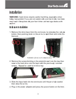
Page 6: ...closure by pressing the release button then pushing down on the arms to eject them and slide the trays out 2 Remove the screws holding in the plastic brace from the tray then secure the hard drive int...

Page 7: ...he PCI Express card by its edges and not the gold connectors 1 Turn your computer off and any peripherals connected to the computer i e Printers external hard drives etc Unplug the power cable from th...

Page 8: ...the drivers Once this has completed click the Finish button Windows Vista 7 1 When the Found New Hardware window appears on the screen click on the Locate and install drivers software recommended opti...

Page 9: ...he installation procedure 3 The Installation Wizard start screen appears Click Install to continue 4 Wait for the installation process to complete 5 Check or uncheck the box Launch the application rig...

Page 10: ...es RAID and Disk Information This section consists of two parts The left side is a tree which shows all controllers on the system and their connected RAID units and hard drives in a hierarchy view Whe...

Page 11: ...e highlighted in green in the tree view and the rebuilding animation will be displayed at the bottom left and right of the window The rebuilding percentage is displayed at the bottom center Clicking t...

Page 12: ...able Selecting the desired RAID type will automatically select the available disks to build the RAID and calculate the RAID capacity It will show the selected disks charts drawn in the cross pattern o...

Page 13: ...d recipients e mail addresses in this page If the mail server needs to authenticate the sender s password when sending mail a username and password may also be required To verify if the entered data i...

Page 14: ...ed disk chart and adjusting the disk size with the slider at the bottom The RAID array can be deleted by checking the Delete RAID check box If the deleted RAID array is password protected the password...

Page 15: ...oss each disk simultaneously Read write performance is increased as a result but failure of any one disk will make the entire array unusable RAID 1 Mirror Mirroring writes the same data across multipl...

Page 16: ...tivity Cooling Fan 1 x 80mm Maximum Data Transfer Rate eSATA 3 0Gb s Supported RAID Modes RAID 0 1 5 1 0 JBOD single Spanning Clone RAID 1 Spare Hard Drive Compatibility 3 5 SATA 1 5 3 0Gbps hard driv...

Page 17: ...alent products at our discretion The warranty covers parts and labor costs only StarTech com does not warrant its products from defects or damages arising from misuse abuse alteration or normal wear a...

Page 18: ...name just a few We offer an unmatched selection of computer parts cables A V products KVM and Server Management solutions serving a worldwide market through our locations in the United States Canada t...

Reviews: