background image

IIn

ns

stta

alllla

attiio

on

n

Installing a Hard Drive in the Enclosure

Use caution when installing a hard drive in the enclosure. Excessive shock or force
could damage the drive and/or the enclosure, resulting in data loss.

CAUTION:

Always ensure that you are properly grounded when handling a hard drive or

the enclosure tray, since electronic components can be damaged by static electricity. If
an anti-static mat or similar product is not available, ground yourself by touching a
computer case or other metal surface for several seconds before handling any
components.

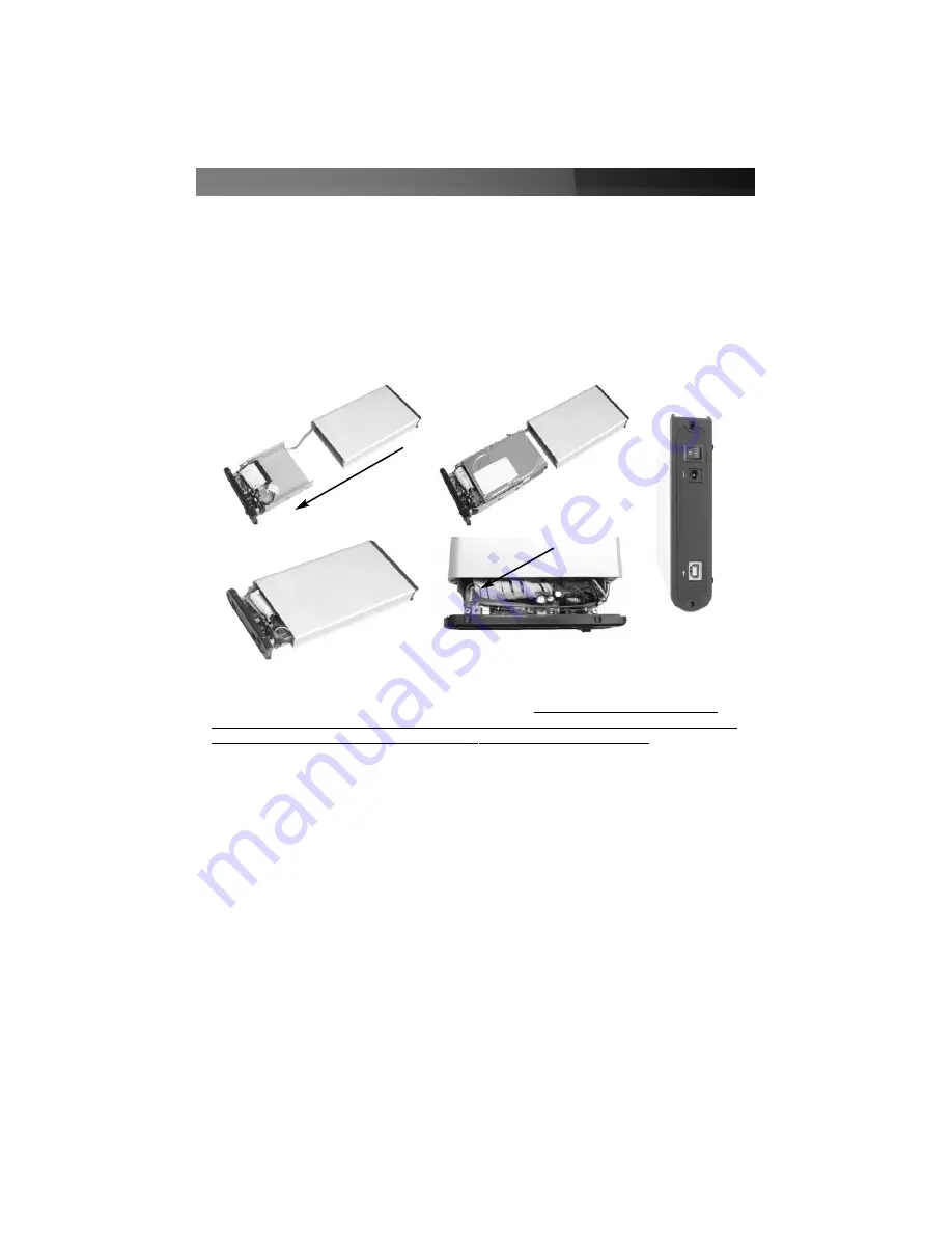
1. Using a small Phillips screwdriver, remove the screws holding the tray in the

enclosure, marked with an “x” in the picture above. Use care when removing the 
screws, as they are extremely small.  After you have removed them, place them in a 
safe location until you are ready to re-insert the tray into the enclosure.

2. Gently slide the tray out of the enclosure in the direction noted above. Insert the hard 

drive in the tray and line up the screw holes on the hard drive with the corresponding 
gaps in the tray.

3. Connect the IDE ribbon cable in the tray so that the red stripe faces pin 1 on the hard 

drive.

4. Connect the LP4-type power connector from the tray to the hard drive.

5. When you have finished connecting the drive to the tray, use standard desktop hard 

drive screws to secure the drive in the tray. The drive should be screwed snugly to the
tray so it does not move.

6. Gently insert the tray into the enclosure, ensuring that the top of the tray matches the 

top of the enclosure and the rail on the tray fits into the corresponding groove in the 
enclosure.

7. Before completely inserting the tray in the enclosure, ensure that the cable that 

Instruction Manual

2

x

x

Summary of Contents for IDECASE35U2B

Page 1: ...InfoSafe Mobile Drive Enclosure IDECASE35U2B Instruction Manual Actual product may vary from photo External USB 2 0 3 5 Hard Drive Enclosure with One Button Backup...

Page 2: ...uipment and receiver Connect the equipment into an outlet on a circuit different from that to which the receiver is connected Consult the dealer or an experienced radio TV technician for help U Us se...

Page 3: ...losure 2 Installing Drivers Windows 98SE 3 Connecting the Enclosure to a Computer 3 Disconnecting the Enclosure from a Computer 4 Installing and Using the One Button Backup Software 4 Installation 4 C...

Page 4: ...rable aluminum finish Can be completely powered through your USB ports for ultimate portability Unique One Button Backup feature automates routine file transfer tasks Backwards compatible with the USB...

Page 5: ...you have removed them place them in a safe location until you are ready to re insert the tray into the enclosure 2 Gently slide the tray out of the enclosure in the direction noted above Insert the ha...

Page 6: ...F file Choose Install from the menu 5 You can now connect the enclosure to your computer Connecting the Enclosure to a Computer This product has been tested with Windows 98 98SE ME 2000 XP 2003 Server...

Page 7: ...not installed the One Button Backup button on the enclosure cannot be used Installation 1 Ensure the enclosure is connected to the computer has been recognized by Windows and is accessible through My...

Page 8: ...ne of the three buttons to configure your options Execute This button will start any tasks that have been configured This has the same function as pressing the One Button Backup button on the rear pan...

Page 9: ...iles to the computer and so on New Creates a new blank task list This option erases all existing tasks Save Saves any changes you have made to the task list Close Closes the task window and returns yo...

Page 10: ...tes and options below Attributes Active The task is active and will be run when the backup button is pushed This setting can also be managed from the Task Status window see below Subdirectory When che...

Page 11: ...on instructions so that Windows can recognize a removable hard drive Also ensure that the drivers for your USB controller have been properly installed If necessary use the USB power cable for addition...

Page 12: ...fer rate 480 Mbits sec A USB 2 0 interface is required for maximum data transfer rates Actual data transfer speeds will vary by configuration Interface Connections Internal 1 x 40 pin 3 5 IDE hard dri...

Page 13: ...25USB_LP Low Profile 2 Port USB 2 0 PCI Card PCI420USB 4 Port USB 2 0 PCI Card PCI425USB Value 4 Port USB 2 0 PCI Card PCI625USB2I Value 6 Port USB 2 0 PCI Card CB2U2F 2 Port USB 2 0 and 2 Port IEEE 1...

Page 14: ...replacement with equivalent products at our discretion The warranty covers parts and labor costs only StarTech com does not warrant its products from defects or damages arising from misuse abuse alte...

Page 15: ...arts cables server management solutions and A V products and serve a worldwide market through our locations in the United States Canada the United Kingdom and Taiwan Visit www startech com for complet...

Reviews: