background image

Instruction Manual

3

Hardware Installation

1.  Ensure your computer system is powered down, and the power cable has been 

disconnected from the Power Supply.

2.  Open your computer case (refer to the computer user manual for details), and place 

the 2.5/3.5in SATA HDD Backplane into an available 5.25” slot, lining up the side 

installation holes on the HSB2535SATBK (pictured below), with installation holes on 

the 5.25” slot inside the computer.

3.  Hold the HSB2535SATBK into place, and fix 4 of the included screws through 

the installation holes on the 5.25” slot, into the side installation holes on the 

HSB2535SATBK.

4.  Connect one of the included “18in SATA cables” from an available SATA host port on 

your motherboard to the “2.5” Drive SATA port” on the back of the HSB2535SATBK. 

5.  Connect one of the included “18in SATA cables” from an available SATA host port on 

your motherboard to the “3.5” Drive SATA port” on the back of the HSB2535SATBK. 

6.  Connect a LP4 Power header from your power supply to the “LP4 Power Connector” 

on the back of the HSB2535SATBK.  If you do not have an LP4 connector available, 

use the included “LP4 to SATA Power Adapter Cable” with an available SATA Power 

Header from your power supply.

Summary of Contents for HSB2535SATBK

Page 1: ...ng de startech com FR Guide de l utilisateur fr startech com ES Gu a del usuario es startech com IT Guida per l uso it startech com NL Gebruiksaanwijzing nl startech com PT Guia do usu rio pt startech...

Page 2: ...eceiving antenna Increase the separation between the equipment and receiver Connect the equipment into an outlet on a circuit different from that to which the receiver is connected Consult the dealer...

Page 3: ...1 Introduction 2 Packaging Contents 2 System Requirements 2 Hardware Installation 3 2 5 3 5in Hard Drive Installation 4 2 5 3 5in Hard Drive Removal 5 How to Use 6 Connecting the Hard Drive 6 LED Indi...

Page 4: ...ct Diagram Front View 1 2 5 Drive bay 2 2 5 Drive bay key hole 3 3 5 Drive bay 4 3 5 Drive bay key hole 5 2 5 3 5in LED indicators Rear View 1 2 5 Drive SATA port 2 3 5 Drive SATA SAS Port 3 LP4 Power...

Page 5: ...1 x 2 5 SATA Hard Drive and or 1 x 3 5 SATA SAS Hard Drive WARNING Hard drives and storage docks require careful handling especially when being transported If you are not careful with your hard disk...

Page 6: ...screws through the installation holes on the 5 25 slot into the side installation holes on the HSB2535SATBK 4 Connect one of the included 18in SATA cables from an available SATA host port on your moth...

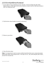
Page 7: ...the included bay keys into the 2 5in 3 5in Drive bay key holes depending on which type of drive you intend to install And Turn the key clockwise into the unlock position 2 Pull the drive door handle...

Page 8: ...rive you intend to install And Turn the key clockwise into the unlock position 2 Pull the drive door handle to open the drive bay 3 Remove your drive 4 Close the drive door Note It is important to eje...

Page 9: ...HSB2535SATBK offers 2 5 3 5in LED indicators to enable you to monitor drive activity The LED will flash while the hard drive is being accessed Do not remove the enclosure from the host computer while...

Page 10: ...compatible with some older operating systems while MBR is supported by newer and older operating systems 3 Once initialized locate the Disk that says it is Unallocated check the listed hard drive capa...

Page 11: ...returned for repair or replacement with equivalent products at our discretion The warranty covers parts and labor costs only StarTech com does not warrant its products from defects or damages arising...

Page 12: ...ts and we quickly deliver them wherever they need to go Just talk to one of our tech advisors or visit our website You ll be connected to the products you need in no time Visit www startech com for co...

Reviews: