4
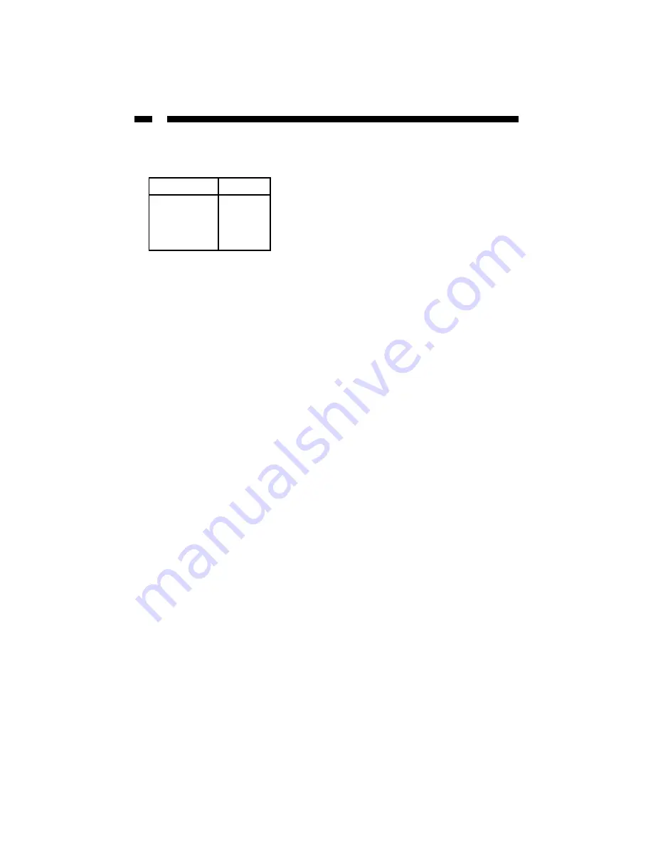
6. Connect the other end of the cable to your motherboard’s USB connectors. The pins
on the cable come in two groups of four wires. The connectors on the cable are:
7. Re-attach your case cover and power on your computer.
8. Your computer will display a message indicating that new hardware has been
detected.
Installing Your Drivers
Windows 98SE and 2000 users -
Follow the onscreen prompts and direct Windows to
the appropriate folder on the driver disk. Windows will install the necessary drivers.
Follow any on-screen prompts to complete the installation.
Windows XP users
- No driver installations required.
Mac OS 9.0
- Follow the on-screen prompts and direct your Mac OS to the appropriate
folder on the driver disk. Click on “Installer” to set up the driver. Follow any on-
screen prompts to complete the installation.
Using Your Card Reader
The LEDs on the panel are your best indication of the card reader’s activity.
• A flashing LED indicates that there is data being transferred to or from the
card.
• The solid LED indicates that the card reader is powered on.
Inserting a Card
1. Turn on your computer.
2. Insert your memory card into the proper slot on the card reader.
3.
Mac
users: A new icon will appear on your desktop.
Windows
users: A new icon will appear in “My Computer.”
4. The card can now be accessed as an extra disk.
Connector
Color
Data +
Green
GND
Black
Data -
White
VCC
Red
Note:
The location and layout of your
motherboard’s USB connectors depends on your
motherboard manufacturer. Improper connection
of wires to the motherboard can result in damage
to the motherboard and/or your card reader.
Make sure you consult your motherboard
manufacturer if you are unsure of the pinout of
your motherboard.
Summary of Contents for 525FCREADAL
Page 11: ...Revised February 03 2004...


