background image

Instruction Manual

7

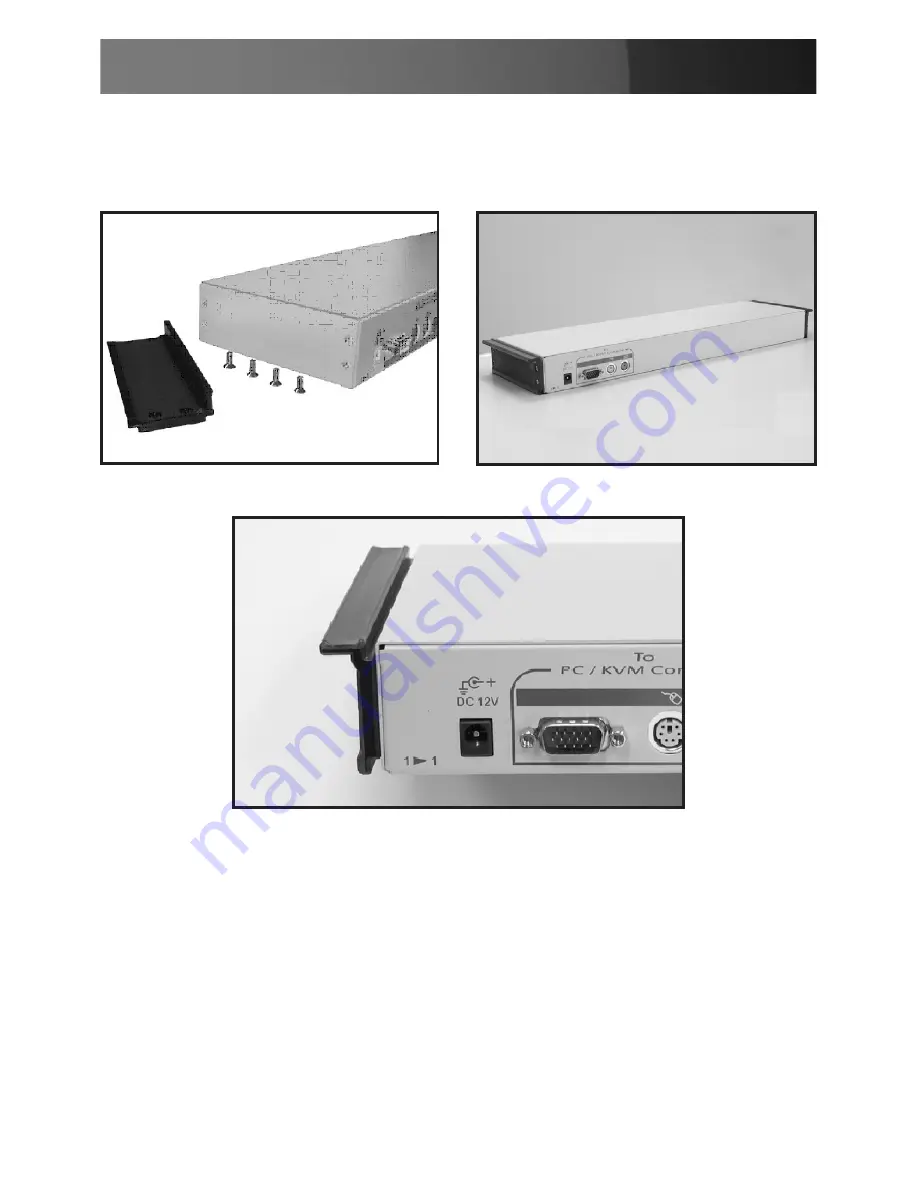
6. Attach the extensions (from the Rear bracket & extension kit) to both  
  sides of the KVM switch module.  Please note the length of the  
  extensions and mount them as shown.  For a 2U module, the  
  extensions are mounted to the lower half of the module.

NOTE: the orientation of the wide side of the extension

7. The rear brackets, extensions and slide rails have a tight fit. Make sure 

you follow these steps for easy installation. 
 
A.Slide the rear brackets onto the extensions.
B. Insert both sliding rails of the assembled drawer into the tight space 
formed by the rear brackets and the extensions. The KVM module 
should be pushed in evenly on both right and left sides.

Summary of Contents for 1UCABCONS

Page 1: ...Cabinet Console 1UCABCONS 1UCABCONS17 1UCABCONS19 ...

Page 2: ...antenna Increase the separation between the equipment and receiver Connect the equipment into an outlet on a circuit different from that to which the receiver is connected Consult the dealer or an experienced radio TV technician for help Use of Trademarks Registered Trademarks and other Protected Names and Symbols This manual may make reference to trademarks registered trademarks and other protect...

Page 3: ...stallation 10 Connecting to a USB Controlled Computer 10 Connecting to a PS2 Controlled Computer 11 Connecting to a KVM Switch 11 Operation 12 Front Panel Functions 12 Keyboard Replacement 13 Touchpad Replacement 14 Specifications 15 Technical Support 17 Warranty Information 17 Screen Quality Pixel Policy 17 ...

Page 4: ...an be mounted on rack cabinets of various depths Features 1UCABCONS Flip open 15 TFT LCD panel supports 1024 x 768 60 70 75 1UCABCONS17 Flip open 17 TFT LCD panel supports 1280 x 1024 60 70 75 1UCABCONS19 Flip open 19 TFT LCD panel supports 1280 x 1024 60 70 75 Standard 19 1U rack drawer Modular design Full 105 key low profile sturdy keyboard built in Standard connectors for PC connection Supports...

Page 5: ...e depth of your cabinet Note the following length is measured between front and rear poles inside the rack cabinet not the outside depth of a rack Please see diagram on the following page Front pole to rear pole distance Depth 1UCABCONS 1UCABCONS17 1UCABCONS19 cm inch cm inch cm inch Minimum 59 23 2 59 23 2 59 23 2 Maximum 96 37 8 96 37 8 123 48 4 Front pole to rear pole distance Depth CABCONS30KI...

Page 6: ...are three major categories PS 2 USB and Sun Interfaces Type PS 2 KVM Model name CAB832DS CAB1631D CAB1631D1U No of Console Ports 2 1 1 No of Computer Ports 8 16 16 OSD Menu Yes Yes Yes Height 1U 2U 1U Cable Type SVPS23N1_xx PS23N1THINxx SVECONxx Continued next page KVM Module Console Drawer KVM Module Console Drawer Depth Depth ...

Page 7: ...S 2 USB No of Console Ports 1 1 No of Computer Ports 8 16 OSD Menu Yes Height 1U 2U Cable Type PS2 SVECONx USB SVECONUSx Type IP KVM Model name CAB1641HDI Interface PS 2 USB No of Console Ports 1 No of Computer Ports 16 OSD Menu Yes Height 1U Cable Type PS2 SVECONx USB SVECONUSx ...

Page 8: ...n them onto the rear vertical poles Both will be removed later 2 Remove the safety stopper from the console drawer The safety stopper is designed to prevent the drawer from sliding out during transportation Please note that once the Safety Stopper is removed the drawer is free to slide out when the console is tilted Be cautious as this could cause injury ...

Page 9: ...rom the front and insert the two slide rails of the assembled drawer into the pockets of the rear brackets 4 Fasten the assembled drawer onto the front brackets using the four screws provided 5 Remove both of the rear brackets The front brackets now hold the assembled drawer ...

Page 10: ... lower half of the module NOTE the orientation of the wide side of the extension 7 The rear brackets extensions and slide rails have a tight fit Make sure you follow these steps for easy installation A Slide the rear brackets onto the extensions B Insert both sliding rails of the assembled drawer into the tight space formed by the rear brackets and the extensions The KVM module should be pushed in...

Page 11: ...Instruction Manual 8 8 Push the KVM switch module evenly toward the drawer 9 Slide the console drawer out and fasten both units together using the screws provided ...

Page 12: ...Instruction Manual 9 10 Make sure the C 36 connectors are firmly connected 11 Connect the power supply to the power jack on the KVM module to complete the assembly 8mm 5 16 C36 Connector ...

Page 13: ...r using either the PS 2 or USB port not both simultaneously Connecting to a USB Controlled Computer Connect the standard VGA cable and a USB A B cable to the computer and 1UCABCONS as shown below The computer can be a USB ready PC Sun HP server or a Mac Male to Female HDB15 for VGA ...

Page 14: ...ng to a KVM Switch When cascading with a KVM switch 1UCABCONS can be used to control up to 16 computers The connection is exactly the same as is shown above see Connecting to a USB Controlled Computer or Connecting to a PS 2 Controlled Computer The only difference is the connection would be made to the CONSOLE PORT could be PS 2 or USB interface of the KVM switch instead of a computer Please choos...

Page 15: ... seconds to select port A 2 Selected Computer Indicator One of the indicators turns red when a corresponding computer is selected by pushbuttons hotkey or OSD menu 3 Local Console in Operation When a computer is accessed through the console this will illuminate green 4 Remote Console in Operation This will illuminate green when a computer is accessed by another set of keyboard mouse monitor connec...

Page 16: ...nance To replace the key board tilt it up locate the mini USB cable underneath the keyboard and unplug it gently While installing the replacement keyboard please ensure that you extend just enough of the cable to keep the keyboard flat inside the tray Please note There is a round hole under the drawer which can be used to pass one finger through allowing for easier removal of the keyboard pushing ...

Page 17: ...e the latch then slide it outwards until the Touch Pad can be lifted up clear from the notches as shown in the figure below right side The Touchpad is attached by a piece of mini USB cable To install the Touchad extend just enough mini USB cable and slide the Touch Pad all the way in till you hear a click sound as it is locked in position Scroll Wheel Area Triangular Marker Left Mouse Button Right...

Page 18: ...lor Pixel Arrangement RGB vertical strip Display Mode Normally White Brightness cd m2 250 center 260 center 250 center Contrast Ratio 350 1 400 1 500 1 Display Color 16 2M colors RGB 6 bits data 16 7M colors RGB 8 bits data User Control OSD Control auto saving Input Signal RGB analog H V separate Plug n Play VESA VESA DDC 1 2B Power Consumption 33W 37W 40W Viewing Angle 70 70 H 60 60 V Typ 80 80 H...

Page 19: ...mperature 20 to 60 C Operating Humidity Relative Humidity 8 95 Non Operating Humidity 95 RH Power Supply Input Voltage Full range 100V AC to 240V AC Regulatory Certifications CE FCC for the product UL TUV CE for power supply Mouse Touch Pad PS 2 Power Management VESA DPMS compliant ON mode 23 2W STANDBY mode 1W SUSPEND mode 1W OFF mode 1W ...

Page 20: ...ce paid for the product Some states do not allow the exclusion or limitation of incidental or consequential damages If such laws apply the limitations or exclusions contained in this statement may not apply to you Screen Quality Pixel Policy During the manufacturing process certain cosmetic imperfections can occur which do not constitute defects in the screen requiring an RMA replacement Defective...

Page 21: ...roducts KVM and Server Management solutions serving a worldwide market through our locations in the United States Canada the United Kingdom and Taiwan Visit www startech com today for complete information about all our products and to access exclusive interactive tools such as the Cable Finder Parts Finder and the KVM Reference Guide StarTech com makes it easy to complete almost any IT or A V solu...

Reviews: