Starrett W2900-1 User Manual Download Page 11

Wireless Indicator User Guide                                                                11                                                                                                     Ver 1.0 


The L. S. Starrett Company                                                                                                                                                3/7/2022 
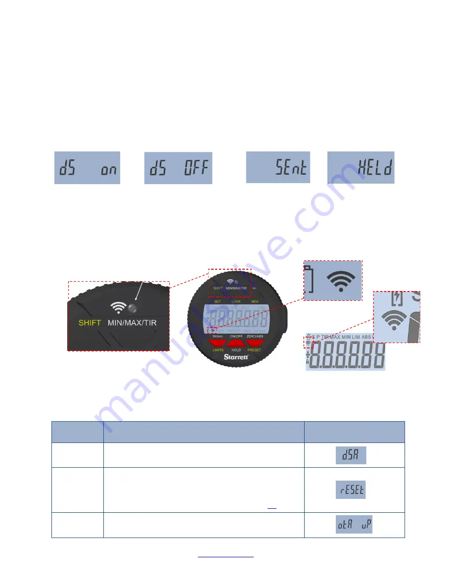
Fig.10B


Fig.10A


3.0 Wireless Functions  

The new Wireless button (Fig.11A) on the 2900 Indicator is used for three functions; turn the wireless on/off, sending a 
reading, and to change/reset a function in profile mode. 

1. You can turn the wireless “DS On” or “DS Off”  by pressing and holding the Wireless Radio Button for more than two        


seconds. The display will show the current wireless state either “DS On” or “DS Off” (Fig.9A

-B). When you release the     

button, the new state, either “DS on” or “DS off” will be shown on the display. The tool will display the new state for 

two seconds, and then the tool will revert back to the current reading.  You can tell that the wireless is on by the           
wireless symbol being visible on the bottom left of the display, Fig.11B. 

3. If you press and hold the Wireless button, you will go into the functions mode and be able to change between the 

three functions. The tool will display either “ On” or “Off” and then the current function. If you continue to hold the      

Wireless button, and then press the In/mm button, the tool will cycle through the functions one at a time. When the   
desired function is displayed release the Wireless button to select the function.  

Fig.11B Wireless 
Symbol 


Fig.9A


Fig.9B


2. When the radio is active, a short press on the radio button will transmit a reading. The display will show either      

“Sent” or “Held”, Fig.10A

-B.  

• 

Sent

, means the data has been successfully sent to the data collection device.  

• 

Held

, means the data is stored in the tool. This will happen when the tool is not able to transfer the data due to;                   

being out of range, or in a bad reception area. The data will be sent when the connection is restored.  

Wireless Radio Button  

Table of Contents


Section 3 Wireless Overview 

Functions 

Description 

Display 

DSA


The tool is ready to communicate with                              
DataSure® Advanced 4.0


RESET 

Reset is used to delete the Security Key used by                       
DataSure® Advanced 4.0 when setting up a wireless tool to                                              
communicate with a Gateway. This is explained on the next 

page, “Communicating with your Wireless Tool” pg.

12


OTA 


(Over the Air) Update: In this profile, the firmware of the tool 
can be updated wirelessly with a PC or Smart Phone. 


Fig.11A


Summary of Contents for W2900-1

Page 1: ...Wireless Indicator User Guide 1 Ver 1 0 The L S Starrett Company 3 7 2022 The L S Starrett Company 121 Crescent Street Athol MA 01331 https www starrett com Wireless Electronic Indicator User Guide ...

Page 2: ...Setting the MIN MAX TIR Function 8 2 3 Resolution Selection 9 2 4 Lock Mode 10 Section 3 Wireless Overview 3 0 Wireless Functions 11 3 1 Communicating with your Wireless Tool 12 3 1 1 Establishing First Communications 12 3 1 2 Moving Tools Between Gateways 12 3 1 2 1 Resetting a Wireless Tools Security Key 12 3 1 2 2 Moving to Another Gateway 1 12 Section 4 Rechargeable Battery 4 0 Rechargeable Ba...

Page 3: ...ery symbol is showing Fig 1A then go to the Rechargeable Battery Care and Maintenance section on page 13 If there is no battery symbol visible then the battery is charged 2 Lightly clean the contact point 3 Fasten the indicator into the appropriate holding device 4 You can turn the indicator on by either pressing the ON OFF button or moving the spindle 5 If applicable pick the unit of measure inch...

Page 4: ...nd release to turn on and Press and hold for 3 seconds to turn off 8 ZERO Press and release the ZERO button and the display will zero The spindle must not be moved until the Zero Sequence has elapsed See Zero Sequence on page 3 instruction 7 9 ABS Enables the ABS mode Press and hold for 2 seconds to activate the ABS mode Press and hold for 2 seconds to exit the ABS mode 10 PRESET Press the SHIFT S...

Page 5: ...item indicates that the item is ready to be SET Changed Fig 5 5 Press the PRESET button to increment the digit value from 1 9 Press the SHIFT SET button to set the digit and move to next digit 6 To set a negative value press the PRESET button when the plus minus sign icon is flashing Fig 5 7 Repeat steps 4 and 5 until all the digits are SET 8 Use the SHIFT SET button to cycle through the digits ba...

Page 6: ...TS button The MIN LIMIT MIN LIM Fig 6C icon will appear in the upper middle of the display Fig 6B C 4 Press the SHIFT SET button The LIMIT LIM icon will flash on off 5 Adjust the gauge using a reference surface to the desired minimum value 6 Press the SHIFT SET button to capture the minimum value The LIMIT LIM icon will stop flashing Continued on next page Fig 6A 1 To enter Min Limit mode Then Pre...

Page 7: ...SET icon will remain on The MAX and MIN icons will stay off as long as the reading is within the set limits If the measurement is beyond the set limits the display will flash and the MIN or MAX LIMIT LIM icon will indicate the direction the limit has been exceeded To exit Press the LIMITS button Fig 7A The MAX LIMIT icon will appear Press Press The LIMIT icon will start flashing Adjust the gauge u...

Page 8: ...isplay 5 Press the ZERO ABS button to measure the part 6 Move the part under the indicator to find the low spot You will know because the value will not change 7 Press the MIN MAX TIR button The MAX icon will appear on the display 8 Press the ZERO ABS button to measure the part 9 Move the part under the indicator to find the high spot You will know because the value will not change 10 Press the MI...

Page 9: ...red If units are set to English then the resolution selection is displayed in inches If the units are set to metric then the resolution selection is displayed in mm Pressing the IN mm button will toggle the selection to the appropriate units This function is not available with the basic type indicators Round Off Condition English In Mode Metric mm Mode Round Off Enabled 000 00005 0000 001 Round Of...

Page 10: ...s the following sequence of buttons 1 Press the SHIFT SET button then press and hold the LOCK button until the lock icon turns on 2 The Lock icon will turn on and stay on Fig 8C Once the lock mode has been activated the operator will not be able to change ABS Normal Mode Limits Units PRESET or MAX MIN TIR The operator will have access to the zero function and viewing of the MIN MAX TIR readings 3 ...

Page 11: ...function If you continue to hold the Wireless button and then press the In mm button the tool will cycle through the functions one at a time When the desired function is displayed release the Wireless button to select the function Fig 11B Wireless Symbol Fig 9A Fig 9B 2 When the radio is active a short press on the radio button will transmit a reading The display will show either Sent or Held Fig ...

Page 12: ...d show Green This means that they have exchanged keys and successfully established a secure link 3 1 2 Moving Tools Between Gateways If a Wireless Tool has established a secure link with a Gateway 1 and you want to move the tool to a new Gateway 2 the tool s security key needs to be reset 3 1 2 1 Resetting a Wireless Tools Security Key 1 First Turn off the Tool and then block it on the Gateway tab...

Page 13: ... plugged in See Fig 13A E for information about the changes to the battery icon and what they mean If you wait to long to recharge the battery the tool will automatically shut down completely to conserve the remaining charge on the battery The battery must have a minimum charge to be recharged If the tool will not turn on with the on off button then you must charge the tool When the tool is plugge...

Page 14: ...tery The tool will flash a sequence of information on the display see the examples below Fig s 14 17 This is normal for the indicator and a brief description of the screens is shown below 2 At the end of the sequence you will see CAL on the display See 4 2 Calibrate below for instructions Fig 14 Full Lamp shows all characters Fig 16 Indicator Version Fig 15 Indicator Number Fig 17 Firmware Version...

Reviews: