Stark KAH 2000 S Operating And Maintenance Manual Download Page 22


Sivu 22 / 23 
 

9.7.


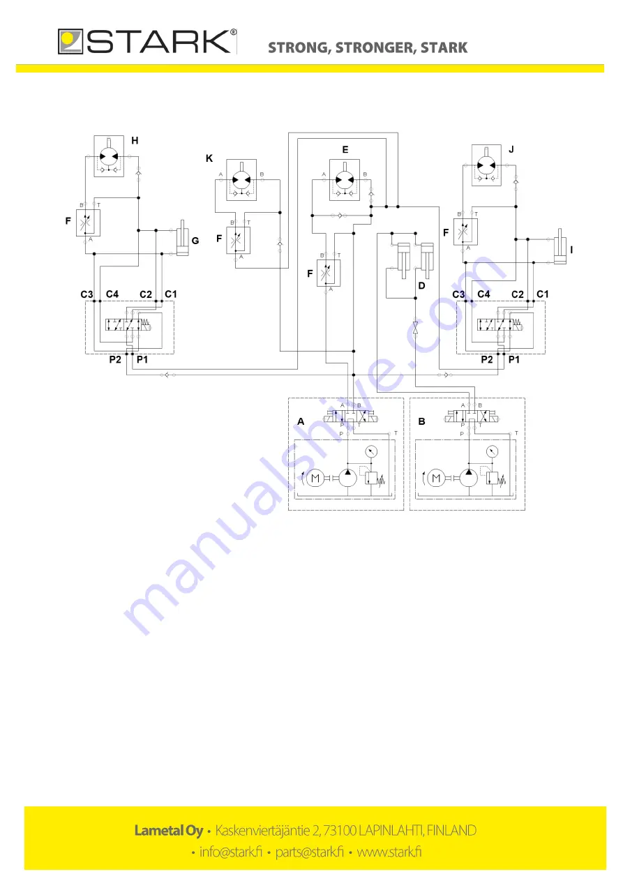
4-hose hydraulics with two side brushes and high-pressure 
washer 


Figure 7. 4-hose hydraulics with two side brushes 


 Base machine control block 

 Base machine control block 2 

 Brush frame lift cylinders 

 Brush roller motor 

 Flow control valve 

 Left side brush, brush lift cylinder 

 Left side brush, brush rotation motor  

 Right side brush, brush lift cylinder 

 Right side brush, brush rotation motor 

 High pressure pump 


Summary of Contents for KAH 2000 S

Page 1: ...Original Operating and maintenance manual Bucket Sweeper S models ...

Page 2: ...sit our webpage www stark fi for the complete product range including new products The manufacturer reserves the right for structural and technical changes without prior notice Therefore some pieces of information given in the manual may have changed after printing this manual Read before use Make sure you know your equipment before you start using it Equipment may be operated only by an individua...

Page 3: ...et sweeper 11 7 5 Detaching the bucket sweeper from the base machine 12 7 6 Accessories 12 8 MAINTENANCE OF THE BUCKET SWEEPER 13 8 1 General safety precautions for use and maintenance 13 8 2 Tightening torque 13 8 3 Daily maintenance 13 8 4 Maintenance after first 10 hours of operation 13 8 5 Maintenance after every 50 hours of operation or weekly 13 8 6 Lubrication points 14 9 Hydraulics 15 9 1 ...

Page 4: ...d Kaskenviertäjäntie 2 73100 LAPINLAHTI Finland tel 358 17 731 565 Declares that the above mentioned equipment meet the provisions of Directive 2006 42 EC on machinery and where applicable comply with the standards SFS EN ISO 12100 1 SFS EN ISO 12100 2 SFS EN 1050 The person authorized to compile technical documentation Lassi Mehtonen Managing director Kaskenviertäjäntie 2 73100 Lapinlahti FINLAND...

Page 5: ...and objects that block your view children use of turn signal when driving NEVER use the machine if there is someone in the danger zone NEVER go under the attachment During maintenance the hydraulics of the base machine MUST be turned off The base machine MUST also be turned off and the parking brake MUST be applied The equipment must be properly supported if maintenance can only be performed by go...

Page 6: ... serial number of your bucket sweeper Product and model _______________________________Serial number___________________________________ 4 2 Maintenance services When replacing parts use original manufacturer spare parts only By using original spare parts you ensure dependable operation of the bucket sweeper and comply with the warranty policy To facilitate the supply of spare parts always inform t...

Page 7: ...IN PARTS OF THE BUCKET SWEEPER Picture 1 Main parts of the device 1 Bucket sweeper frame 2 Brush frame arm 3 Brush frame lifting cylinder 4 Brush roller 5 Adjustment pole 6 Bolt on mudguard 7 Brush rings 8 Wear blade ...

Page 8: ...draulics and electricity 2 Apply parking brake The bucket sweeper is attached to the coupler on the base machine e g a loader Attach the bucket sweeper to the base machine and make sure the locking cotters are secured 3 Turn off the base machine and make sure the parking brake is applied 4 Make sure there is no pressure in the base machine hydraulic system When connecting always make sure the hydr...

Page 9: ...movement paths between the attachment mechanism the base machine and the attachment for collisions Check also the space needed for hydraulic hoses and fittings 6 Check that the brush roll rotates in the direction of the bucket If not switch hose locations in the base machine 7 The rotating speed of the brush roller can be adjusted by the flow control valve Usually appropriate speed is set by using...

Page 10: ...e 3 When the brush rings start to wear lower the brush roller so that brush rings are pressed appr 20mm against the road When the diameter of the brush rings is 50cm they need to be replaced picture 4 NB Make the same adjustments with both poles Otherwise the brush rings will wear unevenly Picture 4 When the diameter is 50cm the brush rings need to be replaced Adjustment pole ...

Page 11: ...unting brackets be careful not to put the entire weight of the brush roller on the motor side 5 Install new brush rings by working in a reverse order Picture 5 Brush roller bearing fastening bolts Picture 6 Brush roller flange fastening bolts 7 4 Transferring the bucket sweeper Lift the bucket sweeper high enough and reduce speed if needed especially on bumpy uneven roads The bucket sweeper or the...

Page 12: ...high pressure pump with container size 155L in model KAH 2000 S and with size 255L in models KAH 2500S and KAH 3000 S Support rollers Side brush with hydraulic lifting right and left side Mechanical side mover Pin Float fitting High pressure washer Note about the watering system 1 Use fresh water only in the watering system 2 Water is sprinkled to the area to be cleared to suppress dusting Place a...

Page 13: ...8 M4 3 3 M5 6 5 M6 11 3 M8 27 3 M10 54 M12 93 M14 148 M16 230 M18 329 M20 464 M22 634 M24 798 M27 1176 M30 1597 M33 2161 M36 2778 M39 3597 Table 1 Tightening torque 8 3 Daily maintenance In order to prevent further damages it is important to inspect the device visually for possible defects Inspect at least the following on a daily basis hydraulic hoses and components for possible leaks general mec...

Page 14: ... 6 Lubrication points Picture 8 Location of grease nipples Picture 9 Grease nipple for the bearing 1 Grease nipples for the hydraulic cylinders 2 Grease nipples for the floating pins 3 Grease nipple for the bearing ...

Page 15: ... system are on the sole responsibility of the client Max pressure 200 bar Max oil flow 100l min Max return line back pressure 80 bar The brush rotation speed is adjusted by the flow control valve If the base machine has a flow control feature the control valve in the attachment can be set to position 10 The bucket sweeper is connected to a 2 hose or a 4 hose hydraulic system In Combi hydraulics lo...

Page 16: ...Sivu 16 23 9 1 2 hose hydraulics Figure 1 2 hose hydraulics A Base machine control block B 6 2 valve C Brush frame lift cylinders D Brush roller motor E Flow control valve ...

Page 17: ...Sivu 17 23 9 2 Combi hydraulics Figure 2 Combi hydraulics A Base machine control block B Brush frame lift cylinders C Brush roller motor D Flow control valve ...

Page 18: ...ith side brush Figure 3 Combi hydraulics with side brush A Base machine control block B 6 2 valve C Brush frame lift cylinders D Brush roller motor E Flow control valve F Side brush brush lift cylinder G Side brush brush rotation motor ...

Page 19: ...her Figure 4 Combi hydraulics with side brush and high pressure washer A Base machine control block B 6 2 valve C Brush frame lift cylinders D Brush roller motor E Flow control valve F Side brush brush lift cylinder G Side brush brush rotation motor H High pressure pump ...

Page 20: ...Sivu 20 23 9 5 4 hose hydraulics Figure 5 4 hose hydraulics A Base machine control block B Base machine control block 2 C Brush frame lift cylinders D Brush roller motor E Flow control valve ...

Page 21: ...brush Figure 6 4 hose hydraulics with side brush A Base machine contol block B Base machine contol block 2 C Brush frame lift cylinders D Brush roller motor E Flow control valve G Side brush brush lift cylinder H Side brush brush rotation motor ...

Page 22: ...ide brushes A Base machine control block B Base machine control block 2 C Brush frame lift cylinders D Brush roller motor E Flow control valve G Left side brush brush lift cylinder H Left side brush brush rotation motor I Right side brush brush lift cylinder J Right side brush brush rotation motor K High pressure pump ...

Page 23: ... as travel and waiting hours daily allowances travel expenses or costs arising from detaching and reinstalling the equipment The manufacturer does not compensate for indirect costs caused by repairs during the warranty period such as lost working hours Original parts replaced during the warranty period shall remain with the manufacturer The client must keep the damaged parts for six 6 months unles...

Reviews: