background image

Federal Communications Commission

Radio Frequency Interference

Statement

This device complies with Part 15 of FCC Rules and Industry Canada licence-exempt RSS standard(s). Operation is 
subject to the following two conditions: 
(1) This device may not cause harmful interference, and 
(2) this device must accept any interference received, including interference that may cause undesired operation.

Le présent appareil est conforme aux CNR d'Industrie Canada applicables aux appareils radio exempts de licence. 
L'exploitation est autorisée aux deux conditions suivantes : 
(1) l'appareil ne doit pas produire de brouillage, et 
(2) l'utilisateur de l'appareil doit accepter tout brouillage radioélectrique subi, même si le brouillage est susceptible 

d'en compromettre le fonctionnement. 

FCC CAUTION
Changes or modifications not expressly approved by the party responsible for compliance could void the user’s 
authority to operate the equipment.
For compliance with the Federal Noise Interference Standard, this equipment requires a shielded cable.
For RF interference suppression, if a ferrite core is provided with this device, affix it to the interface cable.

NOTE: 
This equipment has been tested and found to comply with the limits for a Class A digital device, pursuant to Part 
15 of the FCC Rules. These limits are designed to provide reasonable protection against harmful interference when 
the equipment is operated in a commercial environment. This equipment generates, uses and can radiate radio 
frequency energy and, if not installed and used in accordance with the instruction manual, may cause harmful 
interference to radio communications. Operation of this equipment in a residential area is likely to cause harmful 
interference in which case the user will be required to correct the interference at his own expense.
CAN ICES-3 (A) / NMB-3 (A)

This equipment complies with FCC/IC radiation exposure limits set forth for an uncontrolled environment and 
meets the FCC radio frequency (RF) Exposure Guidelines in Supplement C to OET65 and RSS-102 of the IC radio 
frequency (RF) Exposure rules. This equipment has very low levels of RF energy that it deemed to comply without 
maximum permissive exposure evaluation(MPE). But it is desirable that it should be installed and operated keeping 
the radiator at least 20cm or more away from person's body (excluding extremities: hands,wrists,feet and ankles).

Cet équipement est conforme aux limites d"exposition aux rayonnements énoncées pour un environnement non 
contrôlé et respecte les règles les radioélectriques (RF) de la FCC lignes directrices d'exposition dans le Supplément 
C à OET65 et d"exposition aux fréquences radioélectriques (RF) CNR-102 de l"IC. Cet équipement émet une 
énergie RF très faible qui est considérée conforme sans évaluation de l"exposition maximale autorisée. Cependant, 
cet équipement doit être installé  et utilisé en gardant une distance de 20 cm ou plus entre le dispositif rayonnant et 
le corps (à l"exception des extrémités : mains, poignets, pieds et chevilles). 

-


2


-

Summary of Contents for TSP650II series

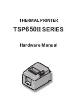
Page 1: ...THERMAL PRINTER TSP650IISERIES Hardware Manual...

Page 2: ...ted in a commercial environment This equipment generates uses and can radiate radio frequency energy and if not installed and used in accordance with the instruction manual may cause harmful interfere...

Page 3: ...NCC NCC NCC NCC 3...

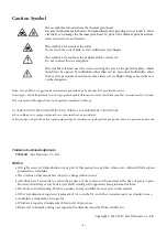
Page 4: ...fter printing do not touch it Static electricity can damage the thermal print head To protect the thermal print head from static electricity do not touch it This symbol is located near the cutter Neve...

Page 5: ...Beyan Megfelel s gi nyilatkozat Overensstemmelseserkl ring F rs kran om verensst mmelse Vaatimuksenmukaisuusvakuutus Konformitetserkl ring Declara o de Conformidade Deklaracja zgodno ci Vyhl senie o...

Page 6: ...g a Paper Roll 15 3 7 Bluetooth Settings For Bluetooth Interface Models only 18 3 8 Setup Precautions 23 4 Attaching the Accessories 25 4 1 Attaching the Holder Plate 25 4 2 Attaching the Rubber Feet...

Page 7: ...nnect to for power should be nearby and unobstructed 4 Make sure that the printer is not exposed to direct sunlight 5 Make sure that the printer is well away from heaters and other sources of extreme...

Page 8: ...nnect this to a tel ephone line Peripheral drive connector Connects to an optional AC adapter Power inlet Connects to a host PC through a cable Interface connector Lights when the printer is online Th...

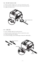
Page 9: ...able Connect the parallel cable to a parallel port on your PC 3 1 2 RS 232C Cable Connect the RS 232C cable to a RS 232C port on your PC 3 1 3 USB Cable Connect the USB cable to a USB port on your PC...

Page 10: ...he product from if you are unsure about what cable to use Before connecting or disconnecting an interface cable be sure to disconnect the AC adapter s power cord from the outlet 3 2 1 Parallel Interfa...

Page 11: ...ct the interface cable to the connector on the rear panel of the printer 3 Tighten the connector screws 3 2 3 USB Cable To connect a USB cable follow the procedure given below 1 Make sure that the AC...

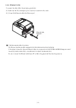
Page 12: ...net port g Link disconnection detection feature The Ethernet interface model is equipped with a link disconnection detection feature If the printer is turned on when an Ethernet cable is not connected...

Page 13: ...connector Pulling the cable excessively could cause damage to the connector Note We recommend that you use the standard AC adapter and power cord If you are not using the optional AC adapter PS60A 24...

Page 14: ...g a modular plug Follow the procedure given below 1 Make sure that the AC adapter s power cord is not connected to the outlet 2 Connect the modular jack plug to the peripheral drive connector on the r...

Page 15: ...oward you 3 Push on both sides of the rear cover to close it Note 1 Be careful not to pull the paper out at an angle because doing so may cause the paper to jam or skew 2 Be sure not to close the prin...

Page 16: ...per roll width 80 0 5 mm 58 0 5 mm Core inner and outer diameters Inner diameter f12 1 mm external diameter f18 1 mm Printed surface Outer edge of roll Note 1 Do not glue or tape the paper roll and sh...

Page 17: ...e paper roll guide firmly into the slot in the printer labeled r58 as shown in the figure below 2 Secure the paper roll guide in place by pushing the section marked as A in the figure Note1 Do not ins...

Page 18: ...Indicates the status of the Bluetooth interface Green on Not connected Green flashing Ready to start pairing Blue on Connected Purple flashing Auto connection ON 3 Pairing will be possible for 60 seco...

Page 19: ...s labor this printer is equipped with the Auto Connection function that automatically requests a con nection from an upper level iOS device that was connected to the printer last time The default sett...

Page 20: ...evice Changing the connected master device Disconnect the Bluetooth connec tion in such a way as to turn OFF the power to the upper level de vice automatically connected Then establish a pairing with...

Page 21: ...izontally again while the LED is flashing 3 The following information is printed After that turn the printer off and then back on again to set Auto Con nection to OFF 4 To make sure Auto Connection is...

Page 22: ...not successful Turn off the printer s power and then try again from step 1 4 Turn off the printer s power switch and delete the pairing setup with the master device Note1 In step 2 if you do not hold...

Page 23: ...tear bar There is a cutter or tear bar inside the paper outlet slot Never put your hand in the slot regardless of whether or not the printer is in operation You must open the printer cover to replace...

Page 24: ...gNa K orC1 maydrasticallyreducetheservicelifeofthethermalprinthead We recommend that you use paper with the following maximum ion densities 500 ppm of Na 150 ppm of K and 300 ppm of Cl For details on...

Page 25: ...n The screws on the wall are not included Use commercially available screws 4 mm diameter that are suitable for the wall material wood steel beam concrete etc n The printer s weight is approximately...

Page 26: ...stalling the printer at a high location make sure that the printer is securely installed to the wall If the printer is not installed securely and falls personal injury or damage to the printer may res...

Page 27: ...y to install the switch cover Only install it if it is necessary for you By installing the switch cover the following become possible Preventing the power switch from being operated by mistake Ensurin...

Page 28: ...vel 2 Level 1 Level 2 Level 1 Level 2 Level 1 Level 2 53 Approx 23 Approx 29 Approx 3 0 Approx 7 7 Approx 29 Approx 23 Approx 7 7 Approx 3 0 65 Approx 23 Approx 29 Approx 2 5 Approx 6 3 Approx 29 Appr...

Page 29: ...e error occurs after you turn the printer back on the printer needs to be repaired Error description POWER ERROR Cause Recovery condition Cutter error Off Flashes at 0 25 second intervals Paper cuttin...

Page 30: ...per while it is being cut This can cause a paper jam 7 2 Removing Paper Jams If a paper jam occurs remove the paper according to the procedure given below 1 Turn the power switch off 2 Open the rear c...

Page 31: ...llow the procedure below Note 1 Be sure to turn off the printer before performing maintenance on the cutter 2 When removing jammed paper be careful not to damage the printer In particular the thermal...

Page 32: ...ermal head surface wipe it clean with a cotton swab or soft cloth dipped in alcohol ethanol methanol or isopropyl 8 2 Platen Rubber Roller Using a dry soft cloth wipe off the dirt from the rubber roll...

Page 33: ...http www starmicronics com support Rev 2 1...

Reviews: