background image

– 7 –

clean the reader/writer.

5. Connect to and Setting External Devices

5-1 RS-232C Interface

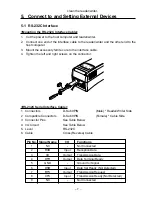
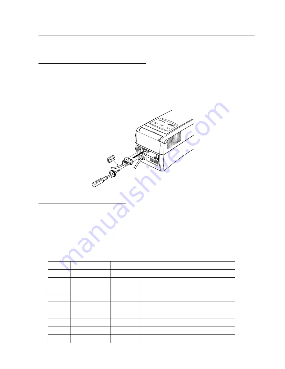
<Mounting the RS-232C Interface Cable>

1. Cut the power to the host computer and reader/writer.

2. Connect one end of the interface cable to the reader/writer and the other end to the

host computer.

3. Mount the accessory ferrite core to the interface cable.

4. Tighten the left and right screws on the connector.

<RS-232C Serial Interface Cable>

1

Connectors

D-Sub 9PIN

(Male) * Reader/Writer Side

2

Compatible Connectors

D-Sub 9PIN

(Female) * Cable Side

3

Connector Pins

See Table Below

4. I/O Circuit

See Table Below

5. Level

RS-232C

6. Cable

Cross (Reverse) Cable

Pin No. Signal Name

I/O

Functions

1

NC

-

Not Connected

2

RXD

Input

Reception Data

3

XD

Output

Transmission Data

4

DTR

Output

Data Terminal Ready

5

GND

-

Ground for Signal

6

DSR

Input

Data Set Ready (Not Detected)

7

RTS

Output

Transmission Request

8

CTS

Input

Transmission Ready (Not Detected)

9

NC

-

Not Connected

Summary of Contents for TCP300 SERIES

Page 1: ...ONICS AMERICA INC 536 Shimizuanatsushinnya Shizuoka 1150 King Georges Post Road Edison NJ 08837 3729 U S A 424 0066 Japan Tel 732 623 5555 Fax 732 623 5590 Tel 0543 47 0122 Fax 0543 48 5013 http www s...

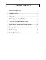
Page 2: ...se 1 2 General Description 4 3 Unpacking 5 4 External Appearance and Part Names 6 5 Connect to and Setting External Devices 7 6 Interface Board Replacement RS 232C to USB 10 7 Cleaning Cards 11 8 Trou...

Page 3: ...er writer in locations where dust or metallic powder can enter the internal reader writer mechanisms Exposing the reader writer to excessive dust will cause it to become hot and can cause electric sho...

Page 4: ...the card and the reader writer See section 7 Cleaning Cards for details on how to clean 3 Do not store cards near devices that generate magnetic fields such as cellular tele phones speakers televisio...

Page 5: ...can cause the reader writer to mis operate electrical shocks or it can cause reader writer failure 15 To ensure reader writer reliability clean the reader writer everyday or when the cleaning lamp ha...

Page 6: ...are used to print erase characters and images freely onto the surface of cards Main Features of the TPC300 Series Reader writer 1 Reads writes card magnetic stripe data 2 Prints deletes the card displ...

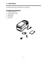
Page 7: ...npacking The following outlines the reader writer and its accessories The reader writer TCP300 Series 1 TCP300 reader writer 2 Cleaning cards 2 cards 3 Cleaning fluid 4 This manual 5 Ferrite core 2 4...

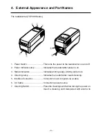
Page 8: ...reader writer power is on 3 Status Indicators Indicates printing ready printing and errors 4 Cleaning Lamp Indicates the reader writer needs cleaning 5 Interface Connector Connects to host computer vi...

Page 9: ...ht screws on the connector RS 232C Serial Interface Cable 1 Connectors D Sub 9PIN Male Reader Writer Side 2 Compatible Connectors D Sub 9PIN Female Cable Side 3 Connector Pins See Table Below 4 I O Ci...

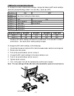
Page 10: ...F DSW 1 2 ON ON OFF OFF Mistaken DIP switch settings will cause the reader writer to mis operate or reader writer failure Be careful when making setting changes To change the DIP switch settings do th...

Page 11: ...e interface cable 3 If a driver for the reader writer is required use the media that was distributed by your agent to install the driver USB Interface Specifications 1 Communication Rating Conforms to...

Page 12: ...w to remove it 4 Insert the USB interface board to the reader writer Note Firmly insert so that the reader writer connector and the interface board con nector are securely connected 5 Tighten the two...

Page 13: ...aces both side of a cleaning card with head cleaning liquid 3 Insert the cleaning card from the normal card insertion inlet 4 Allow the reader writer to sit for approximately one minute before using a...

Page 14: ...erating or other user card incorrectly Head is dirty Clean using a cleaning card Composing system is not operating normally Contact your dealer Reader writer error Trouble when Operating Symptom Possi...

Page 15: ...is open 4 While pulling the mechanism s snap lever green lift the mechanism 5 Remove the card while the cover is open Note Do not touch the thermal head or erasing head There is the danger of getting...

Page 16: ...x 12 24 x 24 48 x 24 24 x 48 48 x 48 Dot Pitch Vertical Direction 0 125 mm Horizontal Direction 0 121 mm Environment Location of Use Indoors Conditions Ambient Temperature 5 to 35 C 20 to 80 RH and Hu...

Reviews: