Star SP6000 SERIES Hardware Manual Download Page 17

-


14


-

4-3.  LED Indications

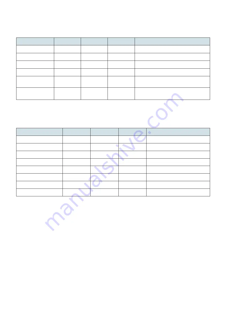
4-3-1.  Normal status

If an error is detected, check the recovery conditions. Recovery is possible without changing the status of the printer.

Status

POWER

MODE

ONLINE

Recovery condition

Status

ON

-

ON

-

Offline

ON

-

OFF

-

High Quality Mode

ON

OFF

-

-

High Speed Mode

ON

ON

-

-

Paper Out

Flashing 1 Sec.

-

OFF

The printer recovers when you set a new paper roll 

and close the cover.

Head high temperature

detection

ON

-

Flashing 1 Sec.

The printer recovers automatically when the ther-

mal head cools.

4-3-2.  Error Indications

Turn off the printer, check the recovery conditions, and then turn on the printer again.

If the same error occurs after restarting the printer, repairs are necessary.

Error description

POWER

MODE

ONLINE

Cause

Watchdog Timer

Flashing 0.5 Sec.

OFF

OFF

Watchdog Timer time up

Mechanical Error

Flashing 0.5 Sec.

ON

OFF

Mechanical failure

Head Thermistor error 

Flashing 0.5 Sec.

OFF

ON

Head Thermistor Detected Erroneous Value

PCB Thermistor error 

Flashing 0.5 Sec.

OFF

Flashing 0.5 Sec.

PCB Thermistor Detected Erroneous Value

Power voltage down

Flashing 0.5 Sec.

Flashing 0.5 Sec.

OFF

ower Voltage Error Value Detected

FLASH Access Error 

Flashing 0.5 Sec.

Flashing 0.5 Sec.

Flashing 0.5 Sec.

FLASH ROM Access Problem

RAM Access Error

Flashing 0.5 Sec.

Flashing 1 Sec.

OFF

RAM Access Problem

Firmware Error

Flashing 0.5 Sec.

Flashing 1 Sec.

Flashing 1 Sec.

-

Note 1: If an unrecoverable error occurs, turn off the printer as quickly as possible.


2: If a power supply voltage error occurs, a power supply fault may be the cause of the error.

 3:


If paper is jammed, turn off the printer, remove the jammed paper, and then turn on the printer again.

           If another type of unrecoverable error occurs, consult your dealer for repairs.

Summary of Contents for SP6000 SERIES

Page 1: ...DOT MATRIX PRINTER SP6000 SERIES Hardware Manual...

Page 2: ...idden The contents of this manual are subject to change without notice All efforts have been made to ensure the accuracy of the contents of this manual at the time of going to press However should any...

Page 3: ...e PC 3 3 2 Connecting the Interface Cable to the Printer 4 3 3 Connecting Power Cable 5 3 4 Turning the Power On 5 3 5 Ribbon Cartridge and Head Gap 6 3 6 Loading a Fanfold Paper 8 3 7 Loading a Cut S...

Page 4: ...bstructed 4 Make sure that the printer is not exposed to direct sunlight 5 Make sure that the printer is well away from heaters and other sources of extreme heat 6 Do not locate the printer in a badly...

Page 5: ...ally Control panel Includesbuttonstooperatetheprinterand lamps indicating the status of the printer Refer to Section 4 Control Panel Rear cover Open when loading paper It is also used to protect the p...

Page 6: ...up 3 1 Connecting the Interface Cable to the PC 3 1 1 Parallel Interface Cable Connect the parallel cable to a parallel port on your PC 3 1 2 USB Interface Cable Connect the USB cable to a USB port on...

Page 7: ...e Before connecting or disconnecting an interface cable be sure to disconnect the power cable from the outlet 3 2 1 Parallel Interface Cable To connect a parallel cable follow the procedure given belo...

Page 8: ...included power cable is for exclusive use with this product Rated voltage 100 240 V Inlet type Frequency 50 60 Hz Take into consideration the noise in the environment that the printer is installed in...

Page 9: ...upper part of the head carriage and move it to the middle of the printer 3 Rotate the ribbon feed knob in the direction of the arrow until the ink ribbon becomes tight 4 Please install the ribbon cass...

Page 10: ...the ink ribbon becomes tight 3 5 2 Setting the Head Gap Referring to the table below adjust the head gap according to the paper type and thickness Head Gap Position Paper Thickness Total Thickness 0...

Page 11: ...opies 3 6 2 Procedure 1 Turn on the power switch of the printer 2 Referring to the figure below remove the rear cover 3 Raising the tractor lever on the outside of the tractor allows the tractor to be...

Page 12: ...t side 5 Set the fanfold paper so that the sprockets match the sprocket holes on the paper and then close the tractors 6 Adjust the position of the right side tractor and then secure it NG NG OK Sproc...

Page 13: ...n to the attaching direction 8 Press the SET EJECT button on the control panel to automatically set the paper to the start printing position For smooth feeding it is recommended to place the continuou...

Page 14: ...position Note If cut paper is fed while fanfold paper is set on the tractors the continuous paper will be released from the tractors To use fanfold paper again reset it onto the tractors Position for...

Page 15: ...Don t touch it because you could be burned CAUTION l We recommend that you unplug the printer from the power outlet whenever you do not plan to use the printer for long periods Because of this you sh...

Page 16: ...r slightly in the feeding direction l Feeds paper slightly in the reverse direction l Changes the auto loading position see table below l Sets the current paper position as the feeding position Power...

Page 17: ...c OFF OFF Watchdog Timer time up Mechanical Error Flashing 0 5 Sec ON OFF Mechanical failure Head Thermistor error Flashing 0 5 Sec OFF ON Head Thermistor Detected Erroneous Value PCB Thermistor error...

Page 18: ...dust from inside the printer and keep each part well maintained Note Make sure that the printer s power switch is turned off when performing maintenance Clean the printer approximately once every 6 m...

Page 19: ...16 6 External Specifications External Dimensions 275 0 mm W 294 0 mm D 163 0 mm H Weight Approx 3 4 kg 14 0 54 0 240 0 261 0 275 0 294 0 163 0 unit mm...

Page 20: ...http www starmicronics com support Rev 1 0...

Reviews: