background image


SPINNER PRO+ MANUFACTURED by  STAR TRAC  OWNER’S MANUAL |  

15 


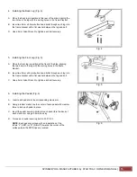
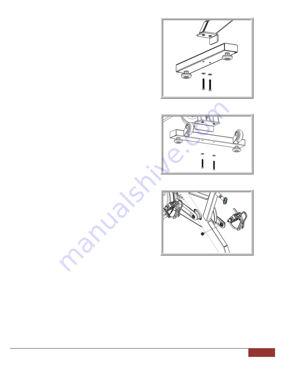
4.  Installing the Back Leg


(Fig. 4)


Fig. 4 


A.  Place the back leg in position at the rear of the bike, aligning the 

two holes in the leg with the mating holes in the frame bracket. 

 
B.  Insert two 8mm x 50mm button head bolts through each leg into 

the frame bracket with a flat washer between the leg and bolt.  


C. 

Use a 5mm Allen Wrench to tighten each bolt securely

.


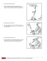
5.  Installing the Front Leg (Fig. 5) 


Fig. 5 

 
A.  Place the front leg in position at the front of the bike, aligning 

the two holes in the leg with the mating holes in the frame 
bracket. 

 
B.  Insert two 8mm x 50mm button head bolts through each leg into 

the frame bracket with a flat washer between the leg and bolt.  

 
C.  Use a 5mm Allen Wrench to tighten each bolt securely.


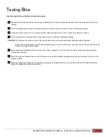
6.  Installing the Pedals (Fig. 6)


Fig. 6 

 
A.   Insert each pedal into the corresponding crank arm. 
 
B.  Using a rubber mallet; tap the center of each pedal with medium 

force to lock each pedal in place. 

 
C.  Insert the pedal securing bolts into each pedal thru the back of 

each crank arm using an 8mm hex key. 

 
D.  Torque each pedal securing bolt to 33-37 lb-ft. 
 

NOTE:

 Each pedal is marked with an indentation of the 

letters “L” (LEFT) or “R” (RIGHT) towards the corner of the 
surface where the SPD clips are located. 


Summary of Contents for SPINNER PRO+

Page 1: ...SPINNER PRO MANUFACTURED BY STAR TRAC OWNER S MANUAL...

Page 2: ...2 SPINNER PRO MANUFACTURED by STAR TRAC OWNER S MANUAL...

Page 3: ...Testing Bike 17 Instructions 18 Seat Adjustment 18 Handlebar Adjustments 19 Pedal Strap Adjustment 19 Resistance Control 19 User Information 20 Bike Setup 20 Training Information 21 Dismounting Bike 2...

Page 4: ...oot Adjustments are covered for three 3 years from the date of purchase Handle Bar Post Plastic Sleeve Seat Post Plastic Sleeve Bottom Bracket Assembly Seat Saddle Assembly and Pop Pin Assembly are co...

Page 5: ...y object hands or feet into any opening or within the area of the flywheel Do use the Spinner only for its intended use as described in this manual Do not attempt to remove any shrouds or modify the S...

Page 6: ...kel voorwerp in de Spinner vallen en steek uw handen of voeten in geen enkele opening van of onder uw Spinner Probeer geen omhulsels te verwijderen of uw Spinner te wijzigen WAARSCHUWING Uw Spinner PR...

Page 7: ...gen oder unter den Spinner fallen und halten Sie H nde und F e von diesen Bereichen fern Unternehmen Sie keinen Versuch irgendwelche Abdeckungen zu entfernen oder den Spinner zu modi fizieren ACHTUNG...

Page 8: ...eixar de observar esta advert ncia pode resultar em ferimentos ou morte PRECAUCIONES Estas notas de seguridad est n dirigidas a usted como el due o de Spinner PRO manufactured by Star Trac Por favor i...

Page 9: ...ctured by Star Trac Var god utbilda alla anv ndare och all personal att f lja dessa s kerhetsanvisningar Man ska uppmuntra alla anv ndare att konsultera sitt h lso progam eller sin tr ningsregim med e...

Page 10: ...10 SPINNER PRO MANUFACTURED by STAR TRAC OWNER S MANUAL Spinner Spinner Spinner Spinner Spinner Spinner PRO manufactured by Star Trac Spinner PRO manufactured by Star Trac...

Page 11: ...SPINNER PRO MANUFACTURED by STAR TRAC OWNER S MANUAL 11 Spinner PRO manufactured by Star Trac Spinner PRO manufactured by Star Trac Spinner Spinner Spinner Spinner Spinner Spinner Spinner Spinner...

Page 12: ...et from the pedals until both the pedals and the flywheel have stopped completely Failure to comply may lead to loss of control and serious injury After exercising turn the resistance knob to increase...

Page 13: ...Multi Sized Open Wrench 1 Tool Kit 1 Take time now to enter your Spinner PRO serial number in the space below serial number is located on the bottom cross member If parts are missing or if you have an...

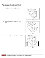
Page 14: ...UAL ASSEMBLY INSTRUCTIONS 1 Unboxing the unit requires turning the sealed box upside down to open the bottom flaps Fig 1 Fig 1 2 Return the opened box back to the upright position Fig 2 Fig 2 3 Expose...

Page 15: ...oles in the leg with the mating holes in the frame bracket B Insert two 8mm x 50mm button head bolts through each leg into the frame bracket with a flat washer between the leg and bolt C Use a 5mm All...

Page 16: ...t all the way into the frame 8 Installing the Seat Post Fig 8 Fig 8 B Insert the seat post into the rear tube of the Spin bike Pull on the seat height adjustment pop pin to lower the seat post all the...

Page 17: ...at different settings CAUTION The flywheel will continue to spin after you pedal and the crank arms and pedals will rotate with the flywheel Brake tension is adjustable using the red resistance knob...

Page 18: ...while reducing the risk of injury Adjust the seat height so that the knee joint is slightly flexed when the extended leg is at the bottom of the pedal stroke Once the proper height has been achieved a...

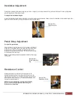
Page 19: ...th the ball of the foot or the widest part of your shoe over the center of the pedals As you pedal concentrate on keeping feet flat which enables a more powerful pedal stroke The front of the shoe may...

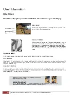
Page 20: ...e effect as moving it higher or lower HANDLEBAR HEIGHT Position the handlebar at the same height as your seat or higher if you feel any discomfort in your back FOOT POSITION Place the balls of your fe...

Page 21: ...es and cardiovascular system for a more intense workout and helps prevent potential injuries from occurring Your warm up should be sufficient once your breathing rate begins to increase and you begin...

Page 22: ...Star Trac recommends having the tools listed Fig 1 available when performing maintenance Tool Purpose Crank Puller Removing cranks pedals Metric Allen Hex Key Wrench Set Tightening or removing variou...

Page 23: ...ned by how consistently you perform the daily maintenance procedures Dry the Spinning bike after each use to remove sweat and moisture It is best to use a liquid non abrasive cleaner diluted with wate...

Page 24: ...alignment Torque flywheel nuts as necessary Remove chain guard and check for loose chain Adjust chain as necessary Inspect each bike for loose assemblies parts bolts and nuts Give particular attention...

Page 25: ...and dry terry cloth dry off any liquid residue Sealing The frame can be sealed by applying a wax or polishing coat that can help repel away liquids like human perspiration Apply the wax or polish per...

Page 26: ...he 10mm open end wrench Figure 2A 2B 5 To loosen the chain turn the adjustment screws on both sides counter clockwise using a 10mm open end wrench 6 While adjusting the chain tension work on both side...

Page 27: ...SPINNER PRO MANUFACTURED by STAR TRAC OWNER S MANUAL 27...

Page 28: ...STAR TRAC 4400 NE 77th Avenue Suite 300 Vancouver WA 98662 Telephone 800 228 6635 714 669 1660 Fax 714 508 3303 http www startrac com Document Number 620 8211...

Reviews: