background image


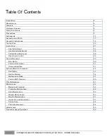
T

able


Of

 C

ontents 


Introduction

4

Manufacturer

4

Warranty

4

Custom er Support

4

Safety Instructions

4

Precautions

5

Safeguards

12

Assem bly and Setup

13

Assem bly Instructions

14

Testing Bike

26

Instructions

27

Seat Adjustm ent

27

Handlebar Adjustm ents

28

Pedal Strap Adjustm ent

28

Resistance Control

29

User Inform ation

30

Bike Setup

30

Training Inform ation

31

Dism ounting Bike

31

Spinner Blade Ion Com puter

32

Orientation

33

Getting Started

34

Maintenance Mode

37

Pairing ANT+ Devices

40

Why Maintenance

41

Maintenance

42

Moving and Leveling

42

Preventive Maintenance

42

Daily Maintenance

42

Weekly Maintenance

43

Monthly Maintenance

43

Inspection and Adjustm ent

43

Fram e Care

44

Parts Replacem ent

44

Adjustm ents

45

Frequently Asked Questions

46


3


 | SPINNER BLADE ION MANUFACTURED by STAR TRAC - OWNER’S MANUAL 


Summary of Contents for SPINNER BLADE ION

Page 1: ...SPINNER BLADE ION MANUFACTURED BY STAR TRAC INSTALLATION OWNER S MANUAL...

Page 2: ...2 SPINNER BLADE ION MANUFACTURED by STAR TRAC OWNER S MANUAL...

Page 3: ...er Information 30 Bike Setup 30 Training Information 31 Dismounting Bike 31 Spinner Blade Ion Computer 32 Orientation 33 Getting Started 34 Maintenance Mode 37 Pairing ANT Devices 40 Why Maintenance 4...

Page 4: ...ot Adjustments are covered for three 3 years from the date of purchase Handle Bar Post Plastic Sleeve Seat Post Plastic Sleeve Bottom Bracket Assembly Seat Saddle Assembly and Pop Pin Assembly are cov...

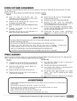
Page 5: ...n the area of the flywheel Do use the bike only for its intended use as described in this manual Do not attempt to remove any shrouds or modify the bike WARNING Your Star Trac Spinner Blade ION is des...

Page 6: ...voeten in geen enkele opening van of onder uw Bike Probeer geen omhulsels te verwijderen of uw bike te wijzigen WAARSCHUWING Uw Spinner Blade ION manufactured by Star Trac is ontworpen voor a robische...

Page 7: ...unft leiten Lesen Sie vor Inbetriebnahme Ihres bike die Bedienungsanleitung vollst ndig durch Ein Missachten dieses Achtungshinweises kann Verletzungen oder den Tod zur Folge haben PRECAUZIONI Queste...

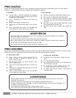
Page 8: ...ntos ou morte PRECAUCIONES Estas notas de seguridad est n dirigidas a usted como el due o de Spinner Blade ION manufactured by Star Trac Por favor instruya a todos sus usuar ios y personal de entrenam...

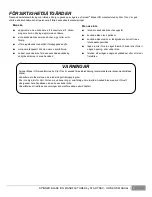
Page 9: ...are och all personal att f lja dessa s kerhetsanvisningar Man ska uppmuntra alla anv ndare att konsultera sitt h lso progam eller sin tr ningsregim med en l kare sluta anv nda bike om man k nner sig y...

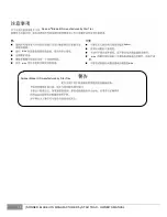
Page 10: ...bike bike bike Spinner bike Spinner Blade ION manufactured by Star Trac Spinner Blade ION manufactured by Star Trac 10 SPINNER BLADE ION MANUFACTURED by STAR TRAC OWNER S MANUAL...

Page 11: ...Spinner Blade ION manufactured by Star Trac Spinner Blade ION manufactured by Star Trac bike bike bike bike bike bike bike bike SPINNER BLADE ION MANUFACTURED by STAR TRAC OWNER S MANUAL 11...

Page 12: ...ave stopped completely Failure to comply may lead to loss of control and serious injury After exercising turn the resistance knob to increase resistance so the pedals will not rotate freely and potent...

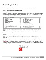
Page 13: ...m Button Head Bolt 1 Load Sensor Plastic Block Covers Kit 1 M5x0 8x12mm Button Head Bolt 1 Tool Kit 1 Multi Sized Open Wrench 1 Take time now to enter your Spinner Blade ION serial number in the space...

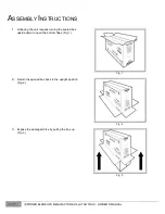
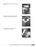
Page 14: ...ing the sealed box upside down to open the bottom flaps Fig 1 Fig 1 2 Return the opened box back to the upright position Fig 2 Fig 2 3 Expose the packaged bike by pulling the box up Fig 3 Fig 3 14 SPI...

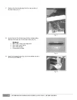
Page 15: ...4 5 Remove the hardware pack and seat from the foam covering the front section of the bike frame Fig 5 Fig 5 6 Tilt the packaged bike frame towards the heavy flywheel and stand on its end Fig 6 Fig 6...

Page 16: ...he corresponding hardware that secures it to the bike frame Fig 8 Hardware M8 x 1 25 x 30mm Hex Head Bolt 8mm Split Lock Washer 8mm Plain Washer Threaded Foot Plate Fig 8 9 Insert the threaded plate F...

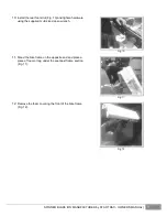
Page 17: ...sized open wrench Fig 10 11 Stand the bike frame on the opposite end and place a piece of foam or rag under the seat post frame section Fig 11 Fig 11 12 Remove the foam covering the front of the bike...

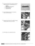
Page 18: ...8mm Plain Washer Threaded Foot Plate Fig 13 14 Insert the threaded plate Fig 14 into the bottom section of the front foot bracket Fig 14 15 Install the front foot strut Fig 15 and tighten hardware us...

Page 19: ...e frame Fig 19 Use the multi sized open wrench to tighten Fig 19 19 Attach the seat slider assembly onto the seat post by pulling the small pull pin located at the underside of the seat post and slidi...

Page 20: ...re inserted wire harness and socket head cap screw at the lower section of the post Fig 22 NOTE Remove the socket head cap screw from the lower section using a 4mm hex key Fig 22 23 Insert the handleb...

Page 21: ...ad the socket head cap stop bolt back into the lower section of the handlebar post Fig 25 NOTE Insert the socket head cap screw to the lower section using a 4mm hex key Fig 25 26 Locate the handlebar...

Page 22: ...t clip and corresponding hardware Fig 29 Hardware M5x0 8x25mm Button Head Bolt M5x0 8x12mm Button Head Bolt Plastic Oval Cap Metal Oval Mount Plate Fig 29 30 Mount the rear oval shaped plastic cover a...

Page 23: ...ION console Fig 31 32 Seat the ION console Fig 32 onto the handlebar and secure the lower metal plate and plastic covers using a 3mm hex key to tighten the two M5 button head screws NOTE The long 25mm...

Page 24: ...esponding hardware Fig 34 Fig 34 35 Insert each pedal into their corresponding crank Fig 35 A NOTE Each pedal is marked with an indentation of the letters L LEFT or R RIGHT towards the corner of the s...

Page 25: ...Fig 37 into each pedal thru the back of each crank arm using an 8mm hex key NOTE Torque settings for each bolt should be between 33 37 lb ft Fig 37 38 Locate the load sensor blocks seated at the cente...

Page 26: ...e load sensor using a 3mm hex key to tighten the two flat head screws Fig 39 40 Using a 2mm hex key tighten the two button head cap screws that secure the Spin badge located at the front of the bike F...

Page 27: ...after you pedal and the crank arms and pedals will rotate with the flywheel Brake tension is adjustable using the red resistance knob in the front of the bike Pressing down on the knob will apply the...

Page 28: ...joint is slightly flexed when the extended leg is at the bottom of the pedal stroke Once the proper height has been achieved adjust the seat forward or back so that when the feet are in the 3 o clock...

Page 29: ...and aft tension handle by turning the handle counterclockwise Move the handlebar forward or back to the desired position then tighten the tension handle by turning clockwise Be sure to tighten the ha...

Page 30: ...ur workout To increase resistance turn the Push Brake System knob clockwise to decrease resistance turn the knob counter clockwise NOTE In case of emergency you may press directly down on the Push Bra...

Page 31: ...tion the handlebar at the same height as your seat or higher if you feel any discomfort in your back FOOT POSITION Place the balls of your feet securely in the toe cages with the ball of the foot or t...

Page 32: ...helps prevent potential injuries from occurring Your warm up should be sufficient once your breathing rate begins to increase and you begin to perspire lightly The warm up period should last about fiv...

Page 33: ...rage power peak power and total ride time or interval time When paired with a compatible device the ION computer will broadcast a data file to the device that will record the ride data including ride...

Page 34: ...unique feature to the Spinner Blade ION is an on board generator which powers the computer eliminating the need to replace batteries as part of the bi annual maintenance routine When the bike is not...

Page 35: ...lutions per minute RPM LINE 3 Power Watts The display will show power to three digits up to 999 Once the rider reaches 1000 watts the computer display for power will flash The amount of watts shown as...

Page 36: ...are as follows LINE 1 Heart Rate displays only when paired to a compatible Ant device LINE 2 Current Cadence RPM LINE 3 Current Power Watts LINE 4 Ride Stage Time LINE 1 Heart rate displays only when...

Page 37: ...verage cadence shown will be averages for the stage not the entire ride Summary Screen Upon completion of the ride or when the rider stops pedaling the ION computer will remain powered for its default...

Page 38: ...as follows Screen 1 Screen 2 Screen 3 Screen 1 displays the current software version loaded into the computer and is for information only Screen 2 is the Distance units screen The default setting for...

Page 39: ...reen 5 is the Battery bAt USE screen This is an information only screen that gives the total amount of time that the battery has provided power to the computer Screen 6 is the Total Distance tot dSt s...

Page 40: ...s The time can be adjusted by pressing and releasing the RESET button The minimum amount of time is 30 seconds The maximum amount of time is 120 seconds The time is adjustable in 5 second increments S...

Page 41: ...conds to make the flashing heart rate icon reappear NOTE The users device must be Ant compatible and capable of receiving the data files broadcast by the Ant chip Users should consult with the documen...

Page 42: ...en performing maintenance Tool Purpose Crank Puller Removing cranks pedals Metric Allen Hex Key Wrench Set Tightening or removing various allen head screws throughout the product Metric Sockets Set Ti...

Page 43: ...ry the bike after each use to remove sweat and moisture It is best to use a liquid non abrasive cleaner diluted with water Wipe Down Cleaning To prevent the build up of rust and other forms of corrosi...

Page 44: ...ard and check for loose chain Adjust chain as necessary Inspect each bike for loose assemblies parts bolts and nuts Give particular attention to the following Tighten all frame base hardware Tighten a...

Page 45: ...the wax or polish per the manufacturer s instructions for best results Parts Repalcement Depending on the use and maintenance of the product certain items can be replaced on a scheduled timeframe The...

Page 46: ...crews on both sides counter clockwise using a 10mm open end wrench 6 While adjusting the chain tension work on both sides of the flywheel Adjust the angle of the flywheel so it is straight front to re...

Page 47: ...ured power output By knowing the difference between the dynamometer power input and watts computer power output we can validate the accuracy of the system The Spinner Blade ION is generally better tha...

Page 48: ...of the flywheel and interconnecting this power to the components It was not realistic to deploy a kit that would fit onto already built bikes because it would mean replacing the flywheel and externall...

Page 49: ...49 SPINNER BLADE ION MANUFACTURED by STAR TRAC OWNER S MANUAL...

Page 50: ...STAR TRAC 4400 NE 77th Avenue Suite 300 Vancouver WA 98662 Telephone 800 228 6635 714 669 1660 Fax 714 508 3303 http www startrac com Document Number 620 8212...

Reviews: