30
STAR
TRAC
S
SERIES
BIKES
O
WNER
’
S
M
ANUAL
M
ANAGER
/
M
AINTENANCE
M
ODE
After using your
STAR TRAC S SERIES BIKE
for a period of time, you may wish to change some of its settings.
MANAGER MODE
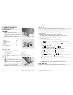
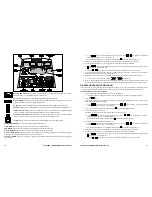
The Manager Settings allow you to query and modify the basic settings of your bike. To enter Manager Settings:
1.
Press and hold the
,
and
keys together.
2.
A beep will sound and “MANAGER SETTINGS” will scroll once across the P
ROFILE
Window.
3.
Release all keys. “SN” will display in the P
ROFILE
Window; the associated numeric value for the parameter will display
in the D
ISTANCE
Window.
NOTE:
The system will automatically exit Manager Settings if no key is pressed for 30 seconds.
The following keys are used to modify MANAGER SETTINGS:
Increase and Decrease Level Keys:
Display the next (Increase) and previous (Decrease) parameters. Keys will
repeat if held.
Numeric Keypad:
Facilitates entry of the desired value for the displayed parameter. These keys
do not
save the
new value – see
OK Key
below.
OK Key:
Updates (saves) the value of the displayed parameter in Flash memory. “UPDATING” will scroll once
across the P
ROFILE
Window while the update is in process. When the update is complete, the P
ROFILE
Window will
show the new value for the parameter.
NOTE:
To exit MANAGER SETTINGS without saving any values or settings, press the Q
UICK
S
TART
key.
NOTE:
Unless otherwise specified, the
Item
(parameter) name is shown in the P
ROFILE
Window, and the value of the parameter is
shown in the D
ISTANCE
Window.
The items that you may display and change with the previous keys are:
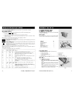
Item
Lowest
Value
Highest
Value
Default
Value
Meaning
SN
0
9999
N/A
Serial Number. S Series Bike serial number (set by factory).
DSW
1.0
99.99
N/A
Display Software. Display panel software version number (set by factory).
NOTE:
Software checksum value is displayed in C
ALORIES
Window.
OHR
0
9999
0
Operating Hours. Total operating hours.
DST
0
9999
0
Distance. Total distance ridden in miles or kilometers, based on current UNx
setting.
UNx
UNE
UNM
UNE
Units. UNE (English) = units of pounds, miles, feet, inches
UNM (Metric) = units of kilograms, kilometers, centimeters
NOTE:
Current Value is shown in P
ROFILE
Window.
TIM
5
99
99
Time. Maximum time in minutes allowed for a program, excluding warm-up
and cooldown.
WGT
1 (lb)
1 (kg)
500 (lb)
226 (kg)
155 (lb)
70 (kg)
Default Weight (to user). Typical weight in lb (UNx = UNE) or kg (UNx =
UNM).
Lxx
N/A
N/A
LEN
Language. Display language; either LEN (English), LGE (German), LSP
(Spanish), LDU (Dutch), LPO (Portuguese), LFR (French), LIT (Italian), LSW
(Swedish) or LKA (Katakana).
LOE
OFF
ON
OFF
Lockout Enable. Enables/disables lockout function.
LOI
001
999
001
Lockout ID. Lockout override identification number.
STAR
TRAC
S
SERIES
BIKES
O
WNER
’
S
M
ANUAL
11
A
SSEMBLY AND
S
ETUP
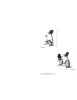
S SERIES UPRIGHT BIKE
ASSEMBLY AND SETUP
Use the following procedures to unpack and assemble your
STAR TRAC
S-UB / S-UBx UPRIGHT BIKE
.
U
NPACKING
Open the shipping carton, remove all parts from the carton and foam
inserts, and verify that the following parts are included in your shipment:
Description
Qty
Bike Frame
1
Display Console Assembly
1
Seat Post Assembly
1
Front Foot
1
Rear Foot
1
Pedals (set of two)
1
Screw, Button Head, M10 X 30
8
Screw, Flat Head, M6 X 16
4
Screw, Socket Head, M6 X 10
1
T
OOLS
R
EQUIRED
Most
STAR TRAC
bikes can be assembled using the following tools:
n
Metric Hex Key Wrenches
n
Metric Open-End Wrenches
n
Metric Ratchet Socket Wrench Set
n
Torque Wrench
n
Channel Lock Pliers
n
Vice Grip Pliers
n
Rubber Mallet
n
Phillips Head Screwdriver
Your
STAR TRAC S-UB / S-UBx UPRIGHT BIKE
includes a hex key set and combination open-end wrench.
A
SSEMBLY
1. Install the Front Foot
NOTE:
The front foot assembly has wheels attached to the front
edge. Be sure the wheels face forward when installing the front foot
assembly.
Stand the bike frame upright and place the front foot assembly
under the frame, aligning the holes in the foot with the holes in
the frame.
NOTE:
It may be necessary to raise the frame slightly to align the
holes in the frame with the mating holes in the front foot.
Using four M10 X 30 button head screws, secure the front foot
assembly to the frame. Tighten all four screws securely.
Step 1


